Facebook
 Google
 GitHub
 Linkedin
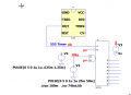
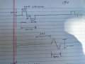
I am new to electronics world and I would like to design a time delay circuit using the 555 timer. The input to the circuit is a square wave with certain frequency and the output should be the same square wave but I need it to be the delayed by 3 to 6 ms. I have also attached the 555 datasheet here in case you need to take a look at it. Additionally, I am open to use any other chip as long as it is accurate in the time delay. Thank you
Attachments
-
1.6 MB Views: 2