[S.T. - 10] Hybrid Amplifier - Common Emitter

Thread Starter

PsySc0rpi0n

Joined Mar 4, 2014
1,773
Hi once more.

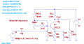
How do I find the Quiescent Point for an hybrid amplifier like the one attached? What do I do to the capacitors and Vsig??? For Small signal analysis we replace voltage sources by their internal impedance and the capacitors by short circuits. What about the Quiescent point?
 

Attachments

Thread Starter

PsySc0rpi0n

Joined Mar 4, 2014
1,773
Why do you call this amplifier a "hybrid"?
To find DC operation point (quiescent point) all you need is to replace all capacitors with a open circuit. Simply you can remove it from the circuit.
You can also remove Vsig.
http://forum.allaboutcircuits.com/threads/transistor-base.81886/#post-585781
When we want to analyse this amplifiers, we use one of the various models available and our teacher calls it that way. The model we use, he calls it hybrid...

Ok, that sounds better...

So, I'm using Thevenin's theorem to simplify the circuit and write down the input and output net equations.

So, using Thevenin I get:

Vth = (Rb2*Vcc)/(Rb1 + Rb2) = (2*12)/(12)=2V
Rth = Rb1//Rb2 = 1.67kΩ

So, the input net equation would be:

Vth + Rth*Ib + Vbe + Re*Ie = 0

And the output equation would be:

Vcc + Rc*Ic + Vce + Re*Ie = 0

Assuming the transistor is in the active region, we can use currents relations to write those equations with only two unkowns like:

Ie = ((hFE+1)/hFE)*Ic

Vth + Rth*(Ic/hFE) + Vbe + Re((hFE+1/hFE)*Ic) = 0

Vcc + Rc*Ic + Vce + Re*((hFE+1/hFE)*Ic) = 0

From here I can calculate Ic and Vce to answer to the Q-Point.

Is this correct?
 
Last edited:

Jony130

Joined Feb 17, 2009
5,488
When we want to analyse this amplifiers, we use one of the various models available and our teacher calls it that way. The model we use, he calls it hybrid...
But hybrid - pi is a small-signal equivalent (replacement) model for transistor alone, not for the amplifier itself.
So, I'm using Thevenin's theorem to simplify the circuit and write down the input and output net equations.

So, using Thevenin I get:

Vth = (Rb2*Vcc)/(Rb1 + Rb2) = (2*12)/(12)=2V
Rth = Rb1//Rb2 = 1.67kΩ

So, the input net equation would be:

Vth + Rth*Ib + Vbe + Re*Ie = 0

And the output equation would be:

Vcc + Rc*Ic + Vce + Re*Ie = 0

Assuming the transistor is in the active region, we can use currents relations to write those equations with only two unkowns like:

Ie = ((hFE+1)/hFE)*Ic

Vth + Rth*(Ic/hFE) + Vbe + Re((hFE+1/hFE)*Ic) = 0

Vcc + Rc*Ic + Vce + Re*((hFE+1/hFE)*Ic) = 0

From here I can calculate Ic and Vce to answer to the Q-Point.

Is this correct?
At first glance everything look OK.
 
Last edited:

Thread Starter

PsySc0rpi0n

Joined Mar 4, 2014
1,773
But hybrid - pi is a small-signal equivalent (replacement) model for transistor alone, not for the amplifier itself.

At first glance everything look OK.
Ok, aside from the names, I need to move on but using those equations I'm going to get a negative Vds. Is it correct?


Edited;

Ok, I did something wrong earlier today. I've re-checked my calcs and now my Q-point is (1.40V; 4.18mA).

Can you help me confirm these values?
 
Last edited:

ericgibbs

Joined Jan 29, 2010
18,872
I've re-checked my calcs and now my Q-point is (1.40V; 4.18mA). Can you help me confirm these values?
hi Psy,
If I follow your circuit correctly, it has a Collector resistor 2K2 and an Emitter resistor of 330R.??
Use Ohms law to check Vc for [2k2 *Ic] and Ve for [330 * Ie] using your assumed Ic of 4.18mA...

E
 

Thread Starter

PsySc0rpi0n

Joined Mar 4, 2014
1,773
hi Psy,
If I follow your circuit correctly, it has a Collector resistor 2K2 and an Emitter resistor of 330R.??
Use Ohms law to check Vc for [2k2 *Ic] and Ve for [330 * Ie] using your assumed Ic of 4.18mA...

E
Morning Mr. EricGibbs.

Yes, Rc = 2k2 Ω and Re = 330 Ω.

So your saying to calculate Vc + Ve and check if this result is equal to Vcc? Is that it?

PS: forgot to put a note in the first post saying that the Rpot is, for now, "out of the circuit"!
 

ericgibbs

Joined Jan 29, 2010
18,872
Dropping 9.2V across the 2200R would give a Vc of 12-9.2= 2.8V at 4.18mA

If you considered a Ic value of say 3mA, that would give Vdrop = 2.2 * 3 = 6.6V , so Vc of 12-6.6 = 5.4V.

The Hint I am trying to give you is what will be the Collector Load line voltage at the Q-point, how can it be 1.4V.?????
 

Jony130

Joined Feb 17, 2009
5,488
OMG. Id and Vds in BJT ??

Vth = Ib*Rth + Vbe + Ie * Re

Ib = Ie/(Hfe +1)

Vth = Ie/(Hfe +1)*Rb + Vbe + Ie * Re

Vth - Ie/(Hfe +1)*Rb + Vbe + Ie * Re = 0

Ie = (Vth - Vbe)/(Re + Rb/(Hfe +1) ) = (2V - 0.6V)/(0.33kΩ + 1.67kΩ/460) = 4.2mA

Vc = Vcc - Ic *Rc = 12V - 4.2mA*10kΩ = -30V

Also notice that for this circuit:

Icmax = Vcc/(Re +Rc) = 12V/(10kΩ + 0.33kΩ) = 1.1mA

All this means that your transistor is in saturation and Ic = Hfe*Ib do not hold anymore .
So, you have chosen wrong operation point.
 

Thread Starter

PsySc0rpi0n

Joined Mar 4, 2014
1,773
OMG. Id and Vds in BJT ??

Vth = Ib*Rth + Vbe + Ie * Re

Ib = Ie/(Hfe +1)

Vth = Ie/(Hfe +1)*Rb + Vbe + Ie * Re

Vth - Ie/(Hfe +1)*Rb + Vbe + Ie * Re = 0

Ie = (Vth - Vbe)/(Re + Rb/(Hfe +1) ) = (2V - 0.6V)/(0.33kΩ + 1.67kΩ/460) = 4.2mA

Vc = Vcc - Ic *Rc = 12V - 4.2mA*10kΩ = -30V

Also notice that for this circuit:

Icmax = Vcc/(Re +Rc) = 12V/(10kΩ + 0.33kΩ) = 1.1mA

All this means that your transistor is in saturation and Ic = Hfe*Ib do not hold anymore .
So, you have chosen wrong operation point.

Ok, I got confused somehow but is just a matter of names!

Anyway, why do you go for Ib = Ie/(hFE + 1) and not Ib = Ic/hFE as we need Ic and Vce and not Ie or Ib????
 

Jony130

Joined Feb 17, 2009
5,488
Because I wanted to show you a alternative approach. Also notice that if we know Ie we eventually know all we want.
Ib = Ie/(Hfe + 1) ; Ic = Ie * Hfe/(Hfe + 1) and because Hfe is very large in your example we can ignore Hfe/Hfe+1 and simply assume Ic = Ie (error will be smaller than 0.21%).
 

Thread Starter

PsySc0rpi0n

Joined Mar 4, 2014
1,773
Because I wanted to show you a alternative approach. Also notice that if we know Ie we eventually know all we want.
Ib = Ie/(Hfe + 1) ; Ic = Ie * Hfe/(Hfe + 1) and because Hfe is very large in your example we can ignore Hfe/Hfe+1 and simply assume Ic = Ie (error will be smaller than 0.21%).
Ok, I understood. But in our classes we always look for Vce and Ic. This will give us our Quiescent point. And when we use the output net equation and assume Ic = 0 we find Vce max and when we assume Vce = 0 we find Ic max. This two values allow us to draw the DC Load Line!

So, I am still not finding correct results:

Input net equation:

Ie = ((hFE+1)/hFE)*Ic

Vth = Rth*Ib + Vbe + Re*Ie
Vth = Rth*(Ic/hFE) + Vbe + Re*((hFE+1)/hFE)*Ic
Ic = (Vth - Vbe)/(Rth/hFE + Re*((hFE+1)/hFE))
Ic = (2 - 0.6)/(1.67/458.7 + 0.33*(459.7/458.7)) = 4.19mA


Output net equation

Vcc = Rc*Ic + Vce + Re*Ie
Vce = Vcc - Rc*Ic - Re*((hFE+1)/hFE)*Ic
Vce = 12-2.2*4.19 - 0.33*(459.1/458.7)*4.19 = 1.396V

What is wrong with my calcs?
 

Thread Starter

PsySc0rpi0n

Joined Mar 4, 2014
1,773
Ahh, your Rc is 2.2kΩ not 10kΩ. And why do you think that your calculations are wrong ?
Well, because a few posts back, Mr. EricGibbs said that Vce couldn't be 1.4V. He did the following: Ic*Vc = 4.18*2.2 = 9.6V. Then Vcc - Vc = 12 - 9.2 = 2.8V so it could not be 1.4V.
 

ericgibbs

Joined Jan 29, 2010
18,872
hi Psy,
Have you read the link in my post #17.?
Regarding Vce
E

EDIT:
I see they are ignoring Re*Ie. Not sure why but I assume that's because voltage drop across Re is minimal, and hence, can be neglected!
Not really.
Think about what you are trying to determine for the Q point ie: Vcollector at the steady state collector current Ic.
 
Top