Facebook
 Google
 GitHub
 Linkedin
HI folks,
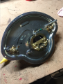
i am looking for a nice big analog meter for a project, i want to run it from DC volts - the exact magnitude is not too important as i can scale either the meter series resistor (assuming a standard permanent magnet voltmeter) or the voltage itself with circuitry if needed.
I see this nice big meter on ebay, the question is- what is the input to an RPM meter likely to be? Yes, i have asked the seller but no response yet and they may not know anyway.
I know automotive RPM meters generally take a pulse - if that's the case, is the meter RC filtering the pulses to get a DC level and then the mechanism is just a standard voltmeter or is there a more complicated mechanism around?
The seller does say int he listing "can be used as a standard analog meter"
thanks for any tips!
")