Rotary encoder with PIC16F877 Microcontroller pin assignments.

Thread Starter

argonrepublic

Joined Feb 21, 2018
8
I have an E-MU XL-7 Sequencer. I purchased it as is. I was told It need a rotary encoder.
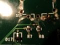
When I looked at the Encoder, it appears that terminal A is attached to a small smd capacitor and then goes to pin 10 on the microcontroller. It appears that terminal B goes to a small smd capactor and them on to pin 12 of THE MICROPROCESSOR ic. but that does not make sense to me. Shouldn't B go to ground? I just assumed
there are no 2 terminal configuration for encoders are there?
 

JohnInTX

Joined Jun 26, 2012
4,787
Welcome to AAC!
If the PIC is in a DIP or PLCC package (/P or /L respectively at the end of part number) then pin 10 is an input (analog or digital) and pin 12 is ground. Pin 12 is NC on a TQFP so that's probably not it.
Are you sure it's an encoder (shaft goes around and around, maybe with detents)? If so, what does it control? For count and direction with a typical quadrature encoder, you need two phases plus ground. If it were a pot feeding the analog input, you'd still need that third pin but maybe that's why you need a new one.
Can you upload clear photo(s) of the part including the underside of the PCB and/or post any part numbers/markings etc.

I looked around for a schematic without success.
 

Thread Starter

argonrepublic

Joined Feb 21, 2018
8
Is it possible to scroll values with only B and C terminals of the encoder in use connected to PIC.? It really appears that the encoder had only 2 traces going to it originally. I'll try to send pictures later on.
 

JohnInTX

Joined Jun 26, 2012
4,787
Is it possible to scroll values with only B and C terminals of the encoder in use connected to PIC.? It really appears that the encoder had only 2 traces going to it originally. I'll try to send pictures later on.
B and C? What happened to A and B?
If one pin is connected to pin 12 of that PIC, that's ground so you only have one pulsing signal from the other pin. That can be used to scroll but only in one direction. A typical quadrature encoder uses 2 signals plus ground to sense pulses and directions like the one described in this datasheet. Are you maybe not seeing some traces on the other side of the PCB?
Of course, it might be something else altogether, but we'd need a part number or photo to know.
 

Attachments

Thread Starter

argonrepublic

Joined Feb 21, 2018
8
B and C? What happened to A and B?
If one pin is connected to pin 12 of that PIC, that's ground so you only have one pulsing signal from the other pin. That can be used to scroll but only in one direction. A typical quadrature encoder uses 2 signals plus ground to sense pulses and directions like the one described in this datasheet. Are you maybe not seeing some traces on the other side of the PCB?
Of course, it might be something else altogether, but we'd need a part number or photo to know.
 

Attachments

JohnInTX

Joined Jun 26, 2012
4,787
I see 3 pins, the center is ground and the two on either side are the A and B phases as described in the PDF I posted. Looks like a typical mechanical encoder to me. If you have a DVM, you can trace the remaining pin to the PIC to confirm. By chance do the dims on that PDF match your part? If not, post an accurate sketch with the outside dims to help us cross a part. You might also try places like Amplified Parts. They have this stuff cross-referenced by brands and model numbers. You can also email them to see if they have one.

Are there any markings on it? A better pic would help.
 

Thread Starter

argonrepublic

Joined Feb 21, 2018
8
used my meter on the encoder. It strobes AB while turning CCW. strobes BC while turning CW. So it iis a typical encoder. I have the original as well as the replacements. The strange thing is that the other side of thoes SMD caps go nowhere. Also pecular is that you have what appears to be two debouncing caps except that they should be at A and C not A and B. I think. Today is the first tome I have had to look into encoders.
Can I make up a non destructive test rig that I can use to trigger the PIC16F877? If so how and which pins should i try and which pins should I avoid? If I can get it to go, I'll just use Point to pint for the wires. I need this thing functional.
Thanks
Mistake above. It was pins 10 and 12.
 

JohnInTX

Joined Jun 26, 2012
4,787
There are only two traces. 1 going to pin 10 the other going to pin 12.
Here's the pinout for the 16F877A-x/L (PLCC). If things are as you say, the encoder is hooked to RE1 and Vdd. I don't know how that would work with the quadrature encoders I am thinking of. I can see how the center common pin could be Vdd but you's still need the other 2 phases for bi-directional sensing. Can you ring out the 3 connections between the encoder pads to the PIC with a DVM to be sure?

For a quick test, if you have an encoder to try, you might be able to put in in the board without soldering. Bend the contact pins out so that they are forced against the sides of the holes, maybe stick a little piece of bare wire in each to jam them in. If you see the display moving both ways, you should be good. Alternately, you can sky-wire it by using small wire like 30ga. wire-wrap wire and tack solder the 30ga. to the holes. When unsoldering, it should come out easily and you can wick the holes clear to install the encoder.
PLCC.jpg
 

Thread Starter

argonrepublic

Joined Feb 21, 2018
8
I was able to retrace my steps. And although the PDF of PIC16F877 I have shows different pinouts than yours, based on your pinouts. I am connected to RC0 and RC1. What I have discovered is that this board is multilayer. I was able to follow test points around the board that do not have visible traces. Now I am going to check for voltage supplying a and C terminals and find a suitable ground for the encoder.
 

MaxHeadRoom

Joined Jul 18, 2013
28,619
two debouncing caps except that they should be at A and C not A and B. I think. Today is the first tome I have had to look into encoders.
I am a litle puzzled as to where the C comes in, a normal quadrature encoder is AB or (BA in the reverse direction).
IOW only two quadrature outputs.
Max.
 
Top