Rittal 31100 Wiring Diagram

Thread Starter

dppagc

Joined Oct 24, 2015
3
Hi everyone,

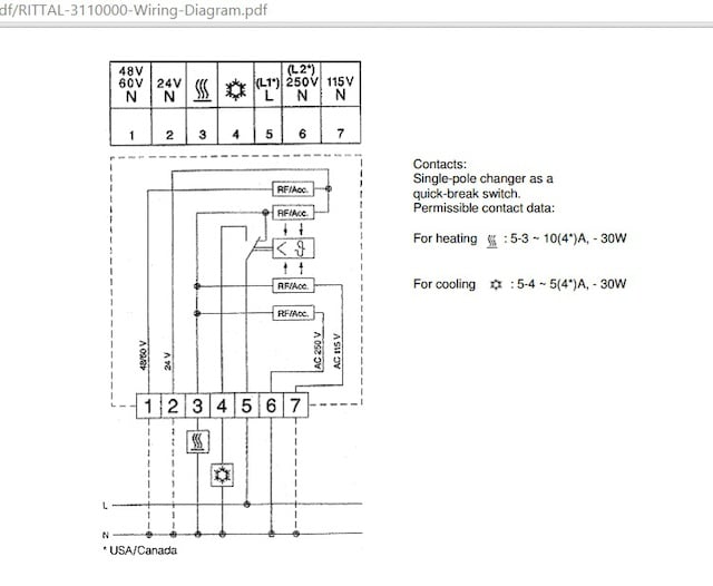
I have a few questions regarding this equipment as seen in the picture.
1) Why is the 250V and 115V at neutral? Shouldnt it be at Live?
2) What is the neutral 48V, 60V and 24V for? I dont think this is a step down transformer.
3) What is for heating 5-3 10(4*)A -30W ??
No matter what voltage I multiply by the current, I cant never get 30W. What does it mean?


MaxHeadRoom

Joined Jul 18, 2013
28,684
The way I interpret it 5 is Live conductor whether 115/250 and 6 would be the other 250v connection for L1 & L2 if both are considered live, if in a country where one side of the 250 is grounded (neutral) then 6 is the 250v N.
If 120v is used then 5 & 7 with 7 being the neutral.
No idea why N is shown on the 60/40/24v
Max.
 
Last edited:

umphrey

Joined Dec 1, 2012
39
In the US some of our more modern HVAC systems have a 120 - 24 VAC transformer and the 24VAC is used to power a digital thermostat. I think pretty much all of them have 24V but some don't bring the wire out to the thermostat.
 

profbuxton

Joined Feb 21, 2014
421
Not familiar with these units but on close examination,I would suggest that terminal 5 is the LIVE(HOT) and 3 is for heating and 4 for cooling. These would switch over according to Thermostat setting. My best guess on the RF/ACC units is they are some kind of element to do with heating control as the appear to be only connected to the heat side of the thermostat.
So depending on your supply one would connect the HOT wire to 5, the Neutral to 6 if using 240v Ac or 7 if using 120v control.
If you have a low voltage control system ie 24v or 48/60 then you would use 5 as HOT or positive if DC and 1 or 2 as Neutral or negative if DC.
I suspect the RF/ac items are some sort of heating element which would affect the thermostat, maybe to provide a hysteresis effect. VERRRY INTERESTING!
 

Thread Starter

dppagc

Joined Oct 24, 2015
3
Not familiar with these units but on close examination,I would suggest that terminal 5 is the LIVE(HOT) and 3 is for heating and 4 for cooling. These would switch over according to Thermostat setting. My best guess on the RF/ACC units is they are some kind of element to do with heating control as the appear to be only connected to the heat side of the thermostat.
So depending on your supply one would connect the HOT wire to 5, the Neutral to 6 if using 240v Ac or 7 if using 120v control.
If you have a low voltage control system ie 24v or 48/60 then you would use 5 as HOT or positive if DC and 1 or 2 as Neutral or negative if DC.
I suspect the RF/ac items are some sort of heating element which would affect the thermostat, maybe to provide a hysteresis effect. VERRRY INTERESTING!
Hi, you are correct. The heat going up in the room will trigger the thermostat. However, can anyone explain this to me:

Category 5 – 3 (heating) AC 10 (4) A (inductive load at cos φ = 0.6) / category 5- 4 (cooling) AC 5 (4) A (inductive load at cos φ = 0.6) / DC = max. 30 W


I practically dont understand this entire sentence. What is AC 10 (4) A (inductive load at cos φ = 0.6)?
I only know that cos 53.1 = 0.6.
When DC = max 30W, how do I know what is the voltage and current to be applied?
 

profbuxton

Joined Feb 21, 2014
421
Looking at the unit data, the RF/AC items shown are part of the "thermal feedback" system. In other words when the contact is made in the "Heat" mode and terminals 1,2,6 and 7 are connected to the correct voltage the RF/ac units will act as heaters for the internal bimetallic strip. This will function in some way to modify the control function of the control.

The sentences you question give the maximum current the the unit will control ie: 10 amps AC in heat mode and 5 amps in cooling mode. The cos Theta refers to the power factor of the controlled load(fan,etc). So the power factor of your load should be better than 0.6. May be listed on your fan motor nameplate?
The 30w rating I am not sure about but it may be the maximum switching load at the nominated voltages, 24V,48V and 60V if that is used for your control circuits ie: at 24v max current switched is 1.25 A.
 
Top