 Facebook
 Google
 GitHub
 Linkedin
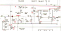
In this AM/FM cassette-corder, the ripple filter Q305 gets 9 VDC from a power supply (the red line going to the right).
In this application, is there any particular reason that the collector of N-P-N transistor is connected to 9 V? What would happen (in theory) if I swap the more negative emitter (8.2 V) with collector?
How this transistor is connected, is it a common base scheme?
In two words, how ripples are being filtered?
Thanks!!
Attachments
-
 381.1 KB Views: 13


