When I use feedback resistance of 100 ohm and feedback capacitance of 2 pF. I am facing ringing effect. So, how do we select the capacitance according to the resistor.
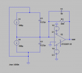
First make sure to check the : "This is an active load" -- check box in the "Advanced" parameters of the current source ::
/!\ 2x 400uA alone does NOT define your voltage - although you might think so or the Simulator might fit in some random value there /!\
\(\uparrow\) put it in between constant voltage \(\uparrow\)
/// or set a series resistance with your current current sources (for it to be able to define the voltage at inverting input)
it also won't hurt to limit your voltage sources with reasonable series resistance ... depending the output power of the Op Amp some 100 down to 10% of the Max. output current
don't copy me (i'm not UHF) -- the sim. just to illustrate what i suggested above (however it may bare no significant effect here)
As always, read the data sheet. Pay particular attention to pages 13 and 14 to determine the correct component values. Be prepared: there's maths involved.
Wideband op amps like the LTC6269-10 are NOT easy to use, and they require extreme care, knowledge and skill to keep them from misbehaving-- like oscillating.
It might be more of an art than a science. The simulation points to several areas of concern
may require isolated copper work and it will be small. I think temporarily having Cf set near resonant condition
might help identify and mitigate the other parasitics then come back rework bypass Cf and R's dielectric standoff,
I have some 'almost working' boards that need a better approach like that.
I can see how how simulation can help declare those issues. Thanks

 11.1 KB Views: 19
 141 KB Views: 17


