Ring Detect Circuit

Thread Starter

jonnythain

Joined Jun 27, 2011
27
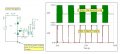
I have made a standard ring detector circuit with an opto-isolator which is identical to this: http://www.epanorama.net/circuits/ringer.gif

The optoisolator connects to a radio transmitter that is operated "momentry"

I have the receiver connected to a 555 timer so there is no issue with actually using the ring pulses to driver another circuit.

The issue i have is that the transmitter doesnt operate as the pulses are too short (it flashes the Tx LED on my Transmitter and if i replicate this manually by pushing the button it still does no operate, it has to be held slightly longer than the blinking LED).

What i want to do is to make the ring pulses long ebough to allow the unit to send the Tx pulse to activate the relay in my receiver. Any ideas how i can do this? I have tried capacitors in parallel and see to be getting nowhere.

Thanks
 

CDRIVE

Joined Jul 1, 2008
2,219
The ring waveform is a sine wave at ~ 20Hz . You should be able to filter it to a near steady state DC (during each ring period) before it's fed to the Opto LED. You could also use a 555 (pulse stretcher) on the output side of the Opto.
 
Last edited:

Thread Starter

jonnythain

Joined Jun 27, 2011
27
Thanks for the reply.

What exactly would i need to do to modify the circuit (with minimal disruption). I dont want to end up blowing my optoisolator.
 

#12

Joined Nov 30, 2010
18,224
That was a quick answer. I will do a slow answer.

35 years ago, I did this with a neon bulb and a cadmuim sulphide photo cell. The neon bulb requires much less current than an LED and the photocell has a long time constant compared to a transistor. That circuit will still work today!

the LED is a current hog. One way to do this is to put a capacitor across D3 and then a resistor to pin 1. The capacitor will store energy and the resistor will let it out slowly. I expect you to do the experimentation to find the sizes of the parts.

Another way is to use a 555 timer that uses external energy to keep the current flowing longer. The circuit is called a "one shot". You can look that up on this site or the internet. The 555 timer is very versatile. The number of ways to connect it are many. I find that hard to store in my head. Lucky we have so many applications available on this site.
 

Thread Starter

jonnythain

Joined Jun 27, 2011
27
That great, i think the missing resistor is where ive been going wrong.

Just to check can i use any resistor/capacitor combination that works, or should i stick in a certain range (im think a capacitor around 22 uf but wouldn't know exactly what value resistor to use, 100R, 1K, 10k ??? )

Many thanks again


CDRIVE

Joined Jul 1, 2008
2,219
35 years ago, I did this with a neon bulb and a cadmuim sulphide photo cell. The neon bulb requires much less current than an LED and the photocell has a long time constant compared to a transistor. That circuit will still work today!
Me too and, like you said, it draws next to nothing from the tel line.
 

CDRIVE

Joined Jul 1, 2008
2,219
I assume that the collector of the opto keys (sinks current) the transmitter. Do you know how much current it needs to sink? This information will greatly help in producing a fairly accurate spice simulation.
 

Thread Starter

jonnythain

Joined Jun 27, 2011
27
No im not sure, i just know how long the optoisolator has to be on for roughly. How does that side of the circuit affect what i am trying to achieve?
 

CDRIVE

Joined Jul 1, 2008
2,219
Not knowing what your collector draws I winged it. I replaced your two 15V Zeners with one 30V model. SW1 is a programmable switch that enabled me to simulate 90V@20Hz ring pulses.
 

Attachments

Last edited:

CDRIVE

Joined Jul 1, 2008
2,219
Looks like I missed your last post. Anyway, you should get even better results than the simulation because your pulling less collector current than I spiced. Now that I think about it, ring periods are closer to 2 seconds than 1 second long. This will charge the cap more on each ring.

Heading out the door. Catch you later...
 

Thread Starter

jonnythain

Joined Jun 27, 2011
27
When i set the above up i get no output at all, if i use a lower capacitor i get the same as what i was getting before? Any ideas?
 

CDRIVE

Joined Jul 1, 2008
2,219
When i set the above up i get no output at all, if i use a lower capacitor i get the same as what i was getting before? Any ideas?
I didn't have a 4N27 to spice this with, so I used a 4N33, which is a Darlington. Darlintons typically have much higher gain.
 

Thread Starter

jonnythain

Joined Jun 27, 2011
27
I so not really sure what to do with certain capacitors cutting the output out all together? Should I be using polarity capacitors as that is what I'm using?
 

CDRIVE

Joined Jul 1, 2008
2,219
C1's polarity is indicated on the schematic. By the way, go back and look at my schematic, as I've added some notes.
 
Top