RF to IR (Velleman MK161) (Noob)

Thread Starter

Wisconsin1000

Joined Apr 24, 2020
5
Hi,

I had a couple questions and would like some noob friendly advice as there isn't a tutorial for this anywhere on youtube…. yet. I noticed in this thread that one could use the MK161 to create an IR device out of my Homegear 110" projector screen remote.

https://forum.allaboutcircuits.com/...ctronics-questions-as-i-am-a-beginner.145973/


1st question: I'm wondering if I can daisy chain the power going into the mk161 to the terminal ends on my remote? I have a 12v 2 amp power supply running into the velleman MK161 for a background on that.

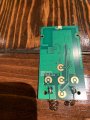
2nd question: Can I solder directly to the copper buttons the two wires from each relay (pic below)? In this case K1 & K3.


I appreciate your help and if you can answer as noob friendly as possible I will credit you in my upcoming youtube vid :)
 

Attachments

I lost what I was going to write, so I'll abbreviate.

Need to know the # of batteries used in the remote? 2 AA would be 3 VDC

Don;t solder to the gold, you will ruin the remote, Scrape away at the green solder mask to expose the copper underneath and solder to that.

I've used the VTL5C1, https://www.amplifiedparts.com/products/optocoupler-vactec-vtl5c1-vactrol-new-old-stock, a now obsolete, but still available, FET/LED with wire leads. Many FET Optocouplers will work. https://www.mouser.com/Optoelectron...couplers/MOSFET-Output-Optocouplers/_/N-awss6

Usually on resistance does not have to be low. Sometime below 1000 ohms is OK. You can try to bridge the pad with some resistors or a potentiometer to see what the highest R across the gold pads will activate the button.

Locktite 444 would be a good product to tack the wires and IC's to the remote. The IC's can be mounted "dead bug" style. "Upside down".

Another thing I do is put a diode and an LM334 (set for 10 mA) in series with the LED side, so any voltage from abput 2-30V will operate the LED and it's reverse polarity protected. You can bring the wires out. You can make some common.

AMPMODU polarized connectors would not be too bad to use.

The MW122A http://www.minute-man.com/acatalog/Multi_Voltage_Economical_Power_Supply.html is a really nice power supply. I've had one on continuously for 10 years or so.

It's a linear supply that's LM337/LM317 based. The voltage selector also selects the secondary winding to get the reduced dissipation.

This https://makezine.com/2012/10/08/a-fine-example-of-dead-bug-style-circuit-wiring/ is exemplary "dead bug" style wiring.
 
Last edited:

Thread Starter

Wisconsin1000

Joined Apr 24, 2020
5
First! Thanks for the response. I have two AAA batteries which should be around 3VDC and I imagine the 12v would blow up this board from the mk161. It sounds like it may be easier to leave the two batteries in the remote. However, I've heard that the batteries drain really quickly which is why I wondered about an external source.


Can you check my diagram below for soldering the 2 channels? I can't figure out where to solder the second point "K3" for the relay.


K1 (brings the screen up)
K3 (brings the screen down)


Thanks again sir! I appreciate it.
Inkedimage_LI.jpg
 

Thread Starter

Wisconsin1000

Joined Apr 24, 2020
5
Last edited:
The ring of K1 and the ring of K2 and the ring of K3 are all the same point.

Solder well away from the gold after scraping away the green layer. There will be copper under the green insulating layer. It's called a solder mask because solder doesn;t stick to it.

The small "holes" are known as vias. They have plating on the edge of the hole connecting the top and the bottom of the board. You might have "better" access there. "Better" meaning not interfering with the keyboard elastomer.

The DC-DC converter that you pictured should work. The switching frequency isn't mentioned. In the rare event it's 38 kHz,then there could be a problem.

I agree it's a pricey supply, but it's nice. I use to power an AM transistor radio so I need a quiet power supply.

You may be able to solder wires through the via's, but lets not try that. it's more difficult.
 

Thread Starter

Wisconsin1000

Joined Apr 24, 2020
5
Wonderful! I'm not too worried about the keyboard elastomer as I won't be using the remote once it's switched to IR. I do appreciate the assistance on this and will post back once I get some supplies in.


Thanks again!
 
You can scrape with a single edged razor blade. "Tin" the copper with solder. "Tin" is word that's generally used even though it probably is from the Tin/lead ERA. It basically means put a layer of solder down before trying to attach a wire.
 
Maybe the control is cheap enough it doesn't matter. Anyway, I'd be a little anal retentive and would probably maintain the current functionality. You don't have to, of course. This https://www.adafruit.com/product/1970 silicone insulated wire is very flexible.

A remote gives you very little wiggle room, but I might bright out the wiresm you gave 3+2-power as either one or two connectors, rubber grommet with an underwriters knot as a strain relief. That leaves you a separate testable remote.

At work, I always built stuff modular and in research environment. In 25 years, I don;t think I even scrapped one thing.
I made temperature controller boxes that had options.
1. they could be wired as 120 or 240.
2. They could have SPI, MVO brought out.
3. They could have a policeman (separate over themperature)
4. They could have power drop out or not by selection.
5. ON/OFF disconnected the heater so there was no shock hazzard in a vacuum.
5A. The unit continued to display temperature.
6. Other thermocouple types could be used
7. twist lock connectors for power in.
8. Had a terminal strip that could be configured for anything.
9. A short cord was necessary to troubleshoot out of the rack.
10. one or 2 load fuses for 120/240 operation, Rear panel normal fuses.

So, it became an appliance.

I made another smaller temperature controller. it consisted of a controller and proprietary SCR unit in a box.
A large 30A switch removed all power. The SPI (Set point in), MVO (Measured value out) signals went to a barrier strip.
Control was INT/EXT and ON/OFF.

The rear panel had thermocouple extension wire and panel mouted mineature connectors.
It had a NEMA plug and could be hard-wired.
This was 120 V only.
Fitted with current limit. Schematics were obtained from the manufacturer and all controllers got the same wiring.
Load fuses were added to reduce the blowing of the $25.00 USD semiconductor fuses.

Eventually, these controllers were not made anymore, but we kept them as portable units.

A new design with ramping was developed by me that did not require a variac, temperature meter, ersatz V and I meters for production, It would have required a 4-20 mA SCR unit, but that and the Variac and srtuff was replaced with a 1500 W DC power supply. 7 of them.

It was unusual to use a DC supply for heating. We got better control, better lifetime, programmability, real V and I measurements, so real power measurements.

One part of the design that wasn't mine was to use a main breaker panel attached to a rack plugged into the wall (60A, 4 wire 208V) to provide 120/208 power. 208 was preferred. Sometimes the PS were 95 to 250. Others were 120/208/240. Sometimes the 208/240 was special order.
 
Top