Facebook
 Google
 GitHub
 Linkedin
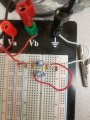
Hello everyone I'm new to this and to circuit design so thank you for your help. My main issue is that my pi network circuit on LTspice does not match the same results as the breadboard circuit i tested. Same components and same parameters, I attached a screen shot of the pie circuit from LTspice, the components consist of: 2V input and 1MHz frequency AC source, with one 100pF, two 220pF, and a third 47pF capacitors, and two 1 microHenry inductors.
At 1MHz frequency the simulation gets about 2.3 V output, the breadboard gets 1.8V output
At 14MHz frequency the simulation gets about 5V output, and the breadboard gets somewhere around the mV (very different)
If anyone could help I would greatly appreciate it, im assuming the error comes from something missing on the simulation circuit i just don't know what.
Daniel
Attachments
-
 142.4 KB Views: 41