Rewinding a toroidal transformer

Thread Starter

Black_Jack

Joined Jun 24, 2020
4
Hi!
I m a engineering student.
I m troubled with rewinding a toroidal transformer. Actually it is amplifier's transformer which is took out some days ago. I was having problem with it so i took it off and as i found the wire of primary winding was broken from its inner end, i unwind the primary coils too. Now i m having a lot of trouble in rewinding because wire is twisted and broken at some points.
Should if buy new round of wire or the old one can work?

How many turns should i have to wind in primary section for an input of 220V AC 50Hz?. The primary has about 21 gauge wire.
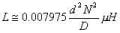
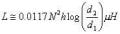
Also i would be very grateful if you will mention the calculation,formulas and procedure to rewind it.
Note: I m very unprofessional so i would rather if answers are in simple form :)

Inner diameter of core: 5.32 cm
Outer diameter of core: 12.2 cm
Height of core: 2.5 cm
Input: 220V AC
Output: 5V , 12V, 33V

Advance thanks!!!
 

jpanhalt

Joined Jan 18, 2008
11,087
Rewinding with used wire is difficult:
1) Copper work hardens, so kinks and other bends will be very hard to avoid. Some of that is just aesthetic.
2) Sharp bends and kinks can damage the insulation and lead to more electrical shorts.

As for number of turns, that would be a guess. When disassembling anything -- electronic, mechanical, etc. -- learn to mark and count so re-assembly is practical. If you know the length of wire that you unwound, you might be lucky rewinding with the same length of new wire. You may end up with fewer turns, as your winding is unlikely to be as dense as the original winding was.

Bottom line: Buy a new one (if possible).
 

jpanhalt

Joined Jan 18, 2008
11,087
PS: If you decide to wind your own, be sure to look up ways to wind a toroid. That is a relatively huge toroid, and you don't want to mess up the new wire as you wind it. You will need a bobbin and a "keeper" to hold the turns you have already made.

Here's an example of a large toroid transformer I wound several years ago for a power supply:
1592991777449.png
 
Last edited:

Delta Prime

Joined Nov 15, 2019
1,311
Also i would be very grateful if you will mention the calculation,formulas
Hello There :) Assuming an air core toroidal inductor.If
one uses a magnetic core as a form to wind the toroid on, the inductance of the toroid can be found by calculating the value from the air core inductor and then multiplying that value by the relative permeability of the magnetic core material.
The inductance for such a toroid can be calculated
where N is the number of turns, R is the mean radius of the form as shown in the figure (in cm), and a is the radius of the windings on the form (in cm)
1592993641591.jpg

1592993336122.jpg

Another formula for the inductance of a circular cross section toroid.where N is the number of turns, D is the mean diameter of the form as shown in the figure (in inches), and d is the diameter of the windings
1592994971686.jpg
1592995211192.jpg
The inductance for a rectangular cross section toroid
1592995477983.jpg
where N is the number of turns, h is the height of the winding (in inches), d1 is the inner diameter (in inches), and d2 is the outer diameter (in inches)
A second formula for a rectangular form toroid
1592995901030.jpg
where N is the number of turns, h is the height of the winding (in cm), r1 is the inner radius (in cm), and r2 is the outer radius (in cm).
 

Attachments

dendad

Joined Feb 20, 2016
4,451
It is always a good idea to count the turns as you take them off.
Just a low voltage secondary will do. For instance, if it is a 12V secondary, and it has 120 turns, then it needs 10 turns per volt.
The primary will be the same. 120V = 1200 turns.
But what the turns per volt on your core was, I do not know. The post above by @Delta prime sounds like the way to go.
And new wire, especially for the primary, is a good idea. Make sure there are no kinks.
 

DickCappels

Joined Aug 21, 2008
10,152
Another method: Make a test winding of something like 20 turns. Drive it with a low frequency (a friend uses a transformer with 3 volts out for this) and measure the voltage on the secondary. The ratio of the voltages will be very close to the turns ratio so you can easily calculate the number of turns you need on the primary.
 

Thread Starter

Black_Jack

Joined Jun 24, 2020
4
See. I used the Russian program Trans50Hz(3700).
I found your results very closer to what i have so i want to go further with you if you donot mind.
In the result you shared, the thickness of primary is stated 0.425mm but originally it has 0.64mm ( say 22 gauge wire).
For 1st secondary winding the wire is 0.58mm (23 gauge) originally.
For 2nd secondary winding the wire is 0.81mm (20 gauge) originally.
For 3rd secondary winding the wire is 1.02mm (18 gauge) originally.

with these infos can we find more accurate result with the program you have? I look forward to you
 

Thread Starter

Black_Jack

Joined Jun 24, 2020
4
PS: If you decide to wind your own, be sure to look up ways to wind a toroid. That is a relatively huge toroid, and you don't want to mess up the new wire as you wind it. You will need a bobbin and a "keeper" to hold the turns you have already made.

Here's an example of a large toroid transformer I wound several years ago for a power supply:
View attachment 210594
yeah its true i donot want to mess up new wires. So can you be more specific on the ways of winding a toroid? What thinks are to be considered and how to wind.
 

jpanhalt

Joined Jan 18, 2008
11,087
The foam plug I show is the "keeper." Soft wood pegs also work well, particularly for smaller toroids. As for the bobbin, image a shuttle cock for weaving. There are fancy ones:
1593016971251.png

And simple ones:
1593017030834.png

I used a simple one. The thinner the wire, the more you can bend it. With the heavy wire I showed and the limited number of turns needed, I just strung it across the living room. When winding ignition coils for miniature CD ignitions, the wire is much finer and 200 or so turns were needed. Then, I used about a 1-ft long shuttle and was able to put all the wire for one winding on it. When you wind the shuttle, you want to avoid sharp bends in the wire as they are difficult to remove.
 

Bordodynov

Joined May 20, 2015
3,177
I found your results very closer to what i have so i want to go further with you if you donot mind.
In the result you shared, the thickness of primary is stated 0.425mm but originally it has 0.64mm ( say 22 gauge wire).
For 1st secondary winding the wire is 0.58mm (23 gauge) originally.
For 2nd secondary winding the wire is 0.81mm (20 gauge) originally.
For 3rd secondary winding the wire is 1.02mm (18 gauge) originally.

with these infos can we find more accurate result with the program you have? I look forward to you
To correctly determine the wire diameter, you need to know the winding currents. More current is more wire thickness. I randomly (at random) set the currents. Give me the data - what currents you need. The rectified voltage (after the diode bridge) is specified in the program.
 

Thread Starter

Black_Jack

Joined Jun 24, 2020
4
To correctly determine the wire diameter, you need to know the winding currents. More current is more wire thickness. I randomly (at random) set the currents. Give me the data - what currents you need. The rectified voltage (after the diode bridge) is specified in the program.
Winding currents
Primary: 1.2 amp
1st secondary: 1 amp
2nd secondary: 2 amp
3rd secondary: 3.2 amp
 

Janis59

Joined Aug 21, 2017
1,834
RE: Dick Cappels: ""Another method: Make a test winding of something like 20 turns..... (and measure the voltages)"".
I am always using very similar method but measuring the input current. Just place where parabolic curve i`=i`(U`) will show the right voltage for those turn count. Yet permissible i(0) max is delivered by simple algorithm - for very very small trafos it may be product of 10% the maximum working current (thus the product of power). For average trafos better to choose sth betw 2% and 5%. For trafos having demands about purity of sinwave (say pre-amps of audio mic PS) then 1% would be mandatory. However for giant trafos - tens and hundreds of kW the 0,1-0,5% is more convenient.

Ah ya, the voltage of course is adjusted at measurment procedure by means of LATR (regulable autotransformer) not a simistor regulator. Hope its clear why.
 
Top