Reverse PSU Voltage protection with fuse and SCR

Thread Starter

aniccame

Joined Sep 25, 2012
4
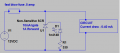
I just wanted to see if anyone had any recommendations for improvements to this simple circuit designed to blow a fuse when a reversed voltage is supplied to the circuit's power input terminals.

A reverse biased SCR is triggered when the wrong voltage is applied. This increases current draw to blow the fuse.

When the SCR is triggered, a negative voltage is seen by the protected circuit equal to the drop across the SCR.

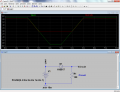
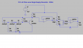
I'm attaching a schematic of the protection circuit and the protected circuit. The protected circuit is a phase shift audio generator with adjustable amplitude output.

Regards,
Alan
 

Attachments

ronv

Joined Nov 12, 2008
3,770
I don't know if your circuit is sensitive to it's power supply voltage, but if it isn't you could just put a diode in series with the supply to block the voltage if it is reversed.
 

MrAl

Joined Jun 17, 2014
11,389
Hi,

A series diode not only drops a variable amount of voltage, it does not actually work at all to protect a power supply against reverse voltage.

It does not work because the diode gets forward biased with either a normal resistive type load or a reverse voltage source, noting the polarity of a reverse connected source applies a negative voltage to the cathode which is exactly what it needs to conduct in the forward direction.

The solution is to use an anti parallel heavy current rated diode and fuse. An SCR is not needed because the diode will not conduct under normal circumstances, only when there is an external source that forces the voltage to go down to about -0.7 volts. Once the diode conducts the fuse blows and the circuit opens.

There is one other small issue here though. That is, you have to make sure your power supply can handle going from full load to zero load in a microsecond or so. Most power supplies can do this, but some may overvoltage when that happens and there is a chance it can blow out anyway, but i think that is rare.

An anti parallel diode without fuse might work too but if the diode blows open it wont help then. If the diode blows short it will, but that's not a chance i like to take so i use a fuse. I recently modified my 150 dollar PS with this mod too because all they had was a 3 amp diode in antiparallel and no fuse.

I suppose it would help if you could get a diode with a rating so high it will always be higher than what you ever connect to it, but if you connect lead acid batteries for charging then you really do need a fuse.
 

Thread Starter

aniccame

Joined Sep 25, 2012
4
I like the p-mosfet idea and I may end up going that route, but I also like the simplicity of a diode and fuse.

I'm sort of looking for a general way to do implement reverse supply protection for most circuits I build. I think I have a p mosfet lying around; I'll have to give it a try.

Alan
 

ronv

Joined Nov 12, 2008
3,770
I think MrAl thought you were trying to protect your power supply from a reversed battery and not your circuit from a reversed supply. So if you can afford to loose the 0.3 volts the diode by itself will work. The PFET will eliminate the loss of the .3 volts.
 

Attachments

crutschow

Joined Mar 14, 2008
34,280
I like the p-mosfet idea and I may end up going that route, but I also like the simplicity of a diode and fuse.
.........................
Why do you consider a MOSFET and a resistor more complex than a diode and a fuse (which would have to be replaced if reverse voltage was accidentally applied)? :confused:
 

Thread Starter

aniccame

Joined Sep 25, 2012
4
I agree with you actually. I'm looking forward to trying the mosfet and I'll probably use it in the future since doesn't require any fuse replacing.
 

crutschow

Joined Mar 14, 2008
34,280
I agree with you actually. I'm looking forward to trying the mosfet and I'll probably use it in the future since doesn't require any fuse replacing.
What is the ON resistance of the P-MOSFET you have?

Note that with a 12V supply you just need one resistor between gate and ground.
 

MrAl

Joined Jun 17, 2014
11,389
Hi,

It does not matter if you are trying to protect the output OR the input, a diode and fuse is the simplest approach and is actually probably the most robust as well.

For the output, the diode goes across the output of the power supply and the fuse goes in series with the output and the load.

For the input (of anything) the diode goes across the input and the fuse goes in series with the input source and the input of the circuit.

So either way, it's a high current diode in antiparallel to the input or output, and a fuse in series with the input source or output load.
Diodes can handle short duration overloads pretty well, and most power mosfets have equivalent reverse diodes built in anyway :)

If you can afford the small voltage drop on the input then yes a series diode will help because it will simply prevent the input from getting any voltage if the input source is reversed. Some applications can handle this pretty well, but power converters and battery operated equipment will usually not do as well with this fix.
 

Thread Starter

aniccame

Joined Sep 25, 2012
4
Thanks for the explanation MrAl - much appreciated.

crutschow - my mosfet has an on resistance of .03A - it's a SUP65P04. Rated for -40v, 65A. I'm going to try it out on the next circuit. I've already mounted my SCR circuit on this one.
 

crutschow

Joined Mar 14, 2008
34,280
........................
crutschow - my mosfet has an on resistance of .03A - it's a SUP65P04. Rated for -40v, 65A. I'm going to try it out on the next circuit. I've already mounted my SCR circuit on this one.
I assume you mean .03Ω. In that case the MOSFET drop will be only .03V per amp of current.
 
Top