Reverse Current building up Voltage

Thread Starter

Electronic_Maniac

Joined Oct 26, 2017
253
Just wanted to clarify my understanding before I design my circuit.

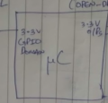
I have an 3.3V LDO Regulator.

Vin = Regulated 5V

Vout = 3.3V

Load Current = 100mA.

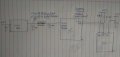
At the output of the LDO, I have a PI Filter Capacitor.

I am having a reverse current of 16uA flowing into the LDO.

Can someone help me to understand how does a reverse current builds up my output voltage from 3.3V to 4.2V.

I am planning to add a Zener rated 3.6V after my Pi filter. I just want to understand how does a small reverse current of 16uA builds up my output voltage from 3.3V to 4.2V?

Does this reverse current hit the inductor of the pi filter and get accumulated near the output side of the inductor to finally bring the output voltage from 3.3V to 4.2V? Or what's happening?

Thanks
 

Thread Starter

Electronic_Maniac

Joined Oct 26, 2017
253
hi EM,
Please post a diagram showing the filter values and the 3.3v loading.
E
I connected a 3.3V Output Micro port to a +5V pullup. That's why the problem has arisen.
Please forgive. There is one attenuator between the Two output caps at the LDO output


Mods Note:
Please don't post the colorful or many color level images file as *.png, the original *.png close to 780KB, and it was cut and changed the file type to *.jpg, and the file size as 90KB.
 

Attachments

ericgibbs

Joined Jan 29, 2010
18,766
hi,
That pull resistor to +5V would pull up the 3.3Vout.
You should add a level shifter between the 3.3 MCU and the 5v logic IC
E
 

Thread Starter

Electronic_Maniac

Joined Oct 26, 2017
253
I just want to understand how does a small reverse current of 16uA builds up my output voltage from 3.3V to 4.2V?

Does this reverse current hit the inductor of the pi filter and get accumulated near the output side of the inductor to finally bring the output voltage from 3.3V to 4.2V? Or what's happening?
 

ericgibbs

Joined Jan 29, 2010
18,766
Does this reverse current hit the inductor of the pi filter and get accumulated near the output side of the inductor to finally bring the output voltage from 3.3V to 4.2V? Or what's happening?
hi,
I do not see a PI filter with an Inductor on your diagram, just two caps in parallel, ie: 22uF and a 10uF on the output of the 3.3V LDO.

E
Are you referring to that Text description of an Inductor.?

Update:
I would say that the resistors at the Logic IC connected to +5V are feeding current back thru the MCU, then back into the 3.3v LDO output.
 
Last edited:

Thread Starter

Electronic_Maniac

Joined Oct 26, 2017
253
hi,
I do not see a PI filter with an Inductor on your diagram, just two caps in parallel, ie: 22uF and a 10uF on the output of the 3.3V LDO.

E
Are you referring to that Text description of an Inductor.?

Update:
I would say that the resistors at the Logic IC connected to +5V are feeding current back thru the MCU, then back into the 3.3v LDO output.
Yes. I am referring to the text description of an Inductor in my diagram as I forgot the draw it before.

And, I understand that the current is feeding back through the MCU and to the LDO output capacitor.
If that current is flowing back, shouldn't I get the +5V (through the 16uA) at the LDO output cap? Why am I getting only 4.2V?

And I=5V/4700ohms=1mA. But why am I getting 16uA? Could you please help and answer
 

Thread Starter

Electronic_Maniac

Joined Oct 26, 2017
253
hi,
I do not see a PI filter with an Inductor on your diagram, just two caps in parallel, ie: 22uF and a 10uF on the output of the 3.3V LDO.

E
Are you referring to that Text description of an Inductor.?

Update:
I would say that the resistors at the Logic IC connected to +5V are feeding current back thru the MCU, then back into the 3.3v LDO output.
I measured the current through the 4.7k pull up resistor and it is showing as 32uA. But shouldn't the current be ((5V-0.7V-3.3V)/4700 = 0.2mA) 0.2mA ?
 

ericgibbs

Joined Jan 29, 2010
18,766
hi,
The internal circuit resistance of the LDO will be sinking some of that leakage current.
This leakage current flows via MCU's internal resistance, causing a voltage drop, so the 5v voltage will be reduced by that resistance.
E

Ref your post #9, it would be 0.2mA IF the bottom of the 4k7 was connected to 0V, but it not, its connected to 0V via the internal resistance of the MCU and the Logic IC.
 

Alec_t

Joined Sep 17, 2013
14,280
In addition to the LDO reg's and the MCU's internal resistances, either component might have internal diodes. Some diodes have appreciable leakage when reverse biased. The 16uA current is thus the result of unknown current paths within the components.
 

DickCappels

Joined Aug 21, 2008
10,152
Electronic_Maniac wrote:

"I connected a 3.3V Output Micro port to a +5V pullup. That's why the problem has arisen.
Please forgive. There is one attenuator between the Two output caps at the LDO output"

"Can someone help me to understand how does a reverse current builds up my output voltage from 3.3V to 4.2V."
upload_2019-10-12_0-4-3.png

The only thing to hold down the output voltage on the output caused by the leakage into the output pin is the feedback resistors in the output stage. Most likely these are very high resistance, so your output can be pulled up pretty high unless there is sufficient load on the output to bring the leakage current down to below the regulators set point (about 3.3V).
 

Thread Starter

Electronic_Maniac

Joined Oct 26, 2017
253
Electronic_Maniac wrote:

"I connected a 3.3V Output Micro port to a +5V pullup. That's why the problem has arisen.
Please forgive. There is one attenuator between the Two output caps at the LDO output"

"Can someone help me to understand how does a reverse current builds up my output voltage from 3.3V to 4.2V."
View attachment 187830

The only thing to hold down the output voltage on the output caused by the leakage into the output pin is the feedback resistors in the output stage. Most likely these are very high resistance, so your output can be pulled up pretty high unless there is sufficient load on the output to bring the leakage current down to below the regulators set point (about 3.3V).
Your last para confuses me more. Till now, I thought that the voltage build-up due to leakage current is due to the output load capacitors and there is an attenuator (600Ohms impedance @ 100MHz and DCR = 0.1Ohms). I believed that the output capacitors are holding the leakage current (capacitor gets charged) which contributes to the voltage buildup. But now, you are saying that the voltage buildup is due to presence of high feedback resistors inside the LDO. Can you clarify in basic terms, which (capacitor or resistor) will hold the charges due to leakage current for voltage build-up? There is also an attenuator inbetween the two output capacitors. So, which will hold the charge due to leakage current for voltage buildup?
 

Thread Starter

Electronic_Maniac

Joined Oct 26, 2017
253
Your last para confuses me more. Till now, I thought that the voltage build-up due to leakage current is due to the output load capacitors and there is an attenuator (600Ohms impedance @ 100MHz and DCR = 0.1Ohms). I believed that the output capacitors are holding the leakage current (capacitor gets charged) which contributes to the voltage buildup. But now, you are saying that the voltage buildup is due to presence of high feedback resistors inside the LDO. Can you clarify in basic terms, which (capacitor or resistor) will hold the charges due to leakage current for voltage build-up? There is also an attenuator inbetween the two output capacitors. So, which will hold the charge due to leakage current for voltage buildup?
@DickChappels
 

DickCappels

Joined Aug 21, 2008
10,152
The voltage is present because of the current from the pull-up resistor going to +5V. It forms a divider with the resistance on the output of the regulator. The capacitor(s) on the output of the regulator slows down the increase in the voltage. You would still have the excess voltage on the output of the regulator is the capacitors were not there, only the voltage would rise much more quickly.

Do you have any loads on the output of the regulator?
 

Thread Starter

Electronic_Maniac

Joined Oct 26, 2017
253
The voltage is present because of the current from the pull-up resistor going to +5V. It forms a divider with the resistance on the output of the regulator. The capacitor(s) on the output of the regulator slows down the increase in the voltage. You would still have the excess voltage on the output of the regulator is the capacitors were not there, only the voltage would rise much more quickly.

Do you have any loads on the output of the regulator?
Thank you. So, you are saying, the capacitor does not hold and accumulate the reverse current for voltage and only the resistors will be the reason for the voltage build up?

In general, capacitors will not play any part in voltage buildup due to reverse current and only the big resistors will be responsible, right?

Yes, I have loads on the output of the regulator. For circuit diagram , please check my post #3 in the thread at the top.

Load current at 3.3V output is 100mA max.
 

DickCappels

Joined Aug 21, 2008
10,152
Not exactly. The reason for the higher voltage than expected on the +3.3 volt supply is because of current from your pull-up resistor. The capacitors absorb the current, which charges the capacitors up a voltage limited by the pull-up resistor and the load, which in this case are the feedback network and apparently the microcontroller.

I cannot make out the last word in the label for the signal going into the left side of the microcontroller (please see attachment). I can read "3.3V GPIO..." but can't make out the last word. If this is the power supply to the microcontroller things make even more sense, since you wrote "+4.2 @ A sleep" and "+3.3 @ A normal".

If that is the positive power supply input of the controller, then it all makes good sense. When the controller is sleeping it draws only a tiny amount of current and the pull-up resistor pulls the +3.3V power supply up to 4.2 volts through the electrostatic discharge protection diodes on the pulled-up input, limited by the high resistance voltage divider in the regulator and to a greater extent, by the power supply input current requirements of the sleeping controller. The capacitors just keep the voltage from changing quickly, which, as bypass capacitors is what they are there for in the first place.

When the controller wakes up it draws more current and the pull-up resistor cannot supply enough current for the controller when the power supply is above 3.3V so the power supply voltage drops down to +3.3V and the power supply adds any necessary current to power the controller. (I added this paragraph to make the description complete).

So...to summarize, the source of the extra 0.9 volts is current from the pull-up resistor. The capacitors just keep the voltage from changing quickly, and the inductor plays no significant role in this phenomenon. Try it -remove the capacitors and you should still see the 4.2 volts remain while the controller sleeps, provided it can get into the sleep state without bypass capacitors.

One thing you might want to check just to be sure is whether the small current on the I/O pin is close to the maximum specified input current for that pin when it is driven above the positive power supply voltage, and whether or not everything else that see this higher voltage, such as the capacitors, is safe at that voltage.

If I were doing this, and it turned out that the small current, which I see as about 40 uA, turned out to be a danger I would probably use a larger pull-up resistor if conditions permit or put a large resistor right between the I/O pin and the rest of the circuitry, or better yet, use a +3.3V pull-up and side-step the problem completely. The reason these would be the preferred solutions is that it might be difficult to find a Zener diode with the right current-voltage curve to fit your application because the leakage is very small.
 

Attachments

Top