Facebook
 Google
 GitHub
 Linkedin
Hi All
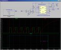
a week ago, I posted "I have a 12v circuit and it has a LED that is flashing repeatedly in a normal output. I want to make a new circuit that detect this flash and turn it into a normal on light or (motor run). If my circuit LED stops flashing, then the light or (motor) would turn it off."
I tried the CD4047BE from http://www.electroschematics.com/6013/retriggerable-monostable/. it is very easy to make with 2 resistors and a capacitor 0.1uf. However, signal in but no signal out... Thanks