 Facebook
 Google
 GitHub
 Linkedin
Hello everyone,
I am restoring a defective MACAP/ELEKTRA bean grinder, probably type MXP. I could not find anything on the net about wiring diagrams and/or PCBs. Also no replacement parts, at least not for the generation of grinder that I have.
I have the idea that there cannot be much that is defective. After all, it is a relatively simple circuit, at least that is what I thought….
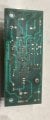
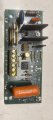
On the circuit board I saw that capacitor C2 is probably missing. I am not a dummy, but determining what value the capacitor should have is too much for me. In the photos several components seem to be missing, but judging by the soldering a component has never been in there.
The wiring diagram:
1+2 are connected with a microswitch. When the ignition is on, they are connected to each other.
2+4 concerns input power supply 220V
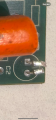
5+6 start capacitor/motor (25uF)
I have already replaced the fuse.
Who can help me determine the capacity of the missing capacitor?
I am restoring a defective MACAP/ELEKTRA bean grinder, probably type MXP. I could not find anything on the net about wiring diagrams and/or PCBs. Also no replacement parts, at least not for the generation of grinder that I have.
I have the idea that there cannot be much that is defective. After all, it is a relatively simple circuit, at least that is what I thought….
On the circuit board I saw that capacitor C2 is probably missing. I am not a dummy, but determining what value the capacitor should have is too much for me. In the photos several components seem to be missing, but judging by the soldering a component has never been in there.
The wiring diagram:
1+2 are connected with a microswitch. When the ignition is on, they are connected to each other.
2+4 concerns input power supply 220V
5+6 start capacitor/motor (25uF)
I have already replaced the fuse.
Who can help me determine the capacity of the missing capacitor?
Attachments
-
 8.5 MB Views: 31
 -
 2.1 MB Views: 33
 -
 3.1 MB Views: 33


