Resistor value when using a PNP to switch 24v from 5v NPN and Schmitt trigger

dl324

Joined Mar 30, 2015
18,446
The pull down on the PNP gets hot, not the one on the NPN that you suggested.
Pull down on what? I suggested putting something smaller directly across the LED, not the LED and it's current limiting resistor. When the LED is on, a 1k resistor would be dissipating 6mW. When off, it would be around 1.5mW (at 1.2V).
 

Irving

Joined Jan 30, 2016
5,195
Are you sure your 2N3906 is the right way round...

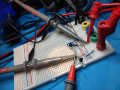
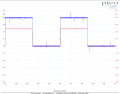
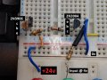
Here's my version of your cct, and I get a few mV and <1uA when off and 24v and 43mA s/c when on, exactly as predicted.

IMAG1446.jpg1674757804091.png
 

dl324

Joined Mar 30, 2015
18,446
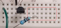
I see you're using one of those inexpensive, to put it kindly, solderless breadboards.
1674757470837.png
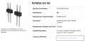
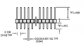
You can use a 5 pin male 0.025" square header to align the clips with holes for easier lead insertion.

For holes indicated, slant the header pins to the left, then lean them to the right to force the clips to align with the holes. I use a male header with long leads and pointed ends.

This is the part I use:
1674757741371.png
1674757815744.png
 

Thread Starter

greycells

Joined Feb 7, 2016
41
I was about to ask that question!


I will try to reverse engineer that picture - unfortunately I have to go out for a bit now.
Would you mind posting a top down picture of your board so I can copy it in the morning? Please!
(are you using 5v & 24v - because my circuits worked at 5v only)
 

Irving

Joined Jan 30, 2016
5,195
I was about to ask that question!


I will try to reverse engineer that picture - unfortunately I have to go out for a bit now.
The 2N3906 is the nearest transistor, emitter to +24 (EBC looking at the flat side). I used a 2N3904 for the NPN which is the same pinout so will appear reversed BUT the 2N2222 is CBE (I didn't have a 2N2222 but other than pinout they are similiar) so it will orient the same way - assuming you maintain good breadboard practice and keep supply and ground roughly on opposite sides!

Yes, 24v (red trace) and 4v drive (blue trace) on scope...

IMAG1448.jpg
 
Last edited:

sghioto

Joined Dec 31, 2017
8,737
Transistor orientation looks correct to me.
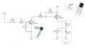
Agree and from the photo I drew this updated schematic. However the TS has stated twice that the LED was OFF when the collector of Q3 was 0v. This is the complete opposite of what should be happening. So something is wrong and this simple circuit is turning into some kind proverbial nightmare.
1674760520883.png
 

sghioto

Joined Dec 31, 2017
8,737
I tested the circuit using a 2N3904 reversed and the LED is constantly ON.
In fact just for fun I switched Q2 and Q3 around. No matter what incorrect combination I used and even installing the transistors backwards the LED was constantly ON. The SPST switch had no effect other then slightly dimming the LED in some configurations as mentioned.
So something is still wrong.
 
Last edited:

dl324

Joined Mar 30, 2015
18,446
In fact just for fun I switched Q2 and Q3 around. No matter what incorrect combination I used and even installing the transistors backwards the LED was constantly ON.
That's because the base-emitter junction breaks down at around 5-6V. Make sure you mark those transistors or throw them away because you've destroyed current gain.
 

Audioguru again

Joined Oct 21, 2019
6,826
Photos of the wires all over the place on a breadboard is a nightmare. If the resistors were neat and tidy then we can see what they are connected to.
The resistor color codes are not correct. Blue, grey, black, black black for 6.8k?? Where is the orange band for the k?
 

Thread Starter

greycells

Joined Feb 7, 2016
41
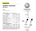
Can I just say a HUGE thank you to everyone who helped me resolve this. I had one transistor image on my phone and one on my laptop - one was for a 2N2222A (the one I'm using) and the other a P2N2222. The collectors and emitters are opposite of each other - I was blaming my brain fog for not being able to remember the pinouts - thank you @Irving for making me re-check, double check and then check again.
I also took @dl324's advice and threw out all the transistors that I may or may not have wired incorrectly and lo and behold, it works as expected.
So thank you again for your patience - I have learned a lot: cutting down resistor leads makes the breadboard connections a whole lot more reliable, badly connected transistors won't work as expected but mostly I've learned that very similar component numbers can really bite you on the bum but AAC is still a really friendly place!
 

dl324

Joined Mar 30, 2015
18,446
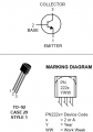
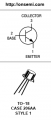
I had one transistor image on my phone and one on my laptop - one was for a 2N2222A (the one I'm using) and the other a P2N2222. The collectors and emitters are opposite of each other
There are 3 pinouts for TO-92: EBC, CBE, and BCE. 2N and BC are reversed from each other, 2SC put the collector in the middle. But watch out for reversed pinout devices. I have a bag of some BC transistor that was marked reverse pinout.

That 2N2222A in TO-92 always gives me heartburn. 2N2222A was always in a TO-18 package. What were they thinking?

From Texas Instruments 1973 Transistor and Diode Databook:
1674836186661.png
 
Last edited:
Top