Resistor value when using a PNP to switch 24v from 5v NPN and Schmitt trigger

dl324

Joined Mar 30, 2015
18,447
I put a 22k resistor (R102) between collector and GND of Q2 but only by reducing it further to 4.7k did the LED turn off. However there is still 1.2v across the resistor when the LED is off but if I reduce the value any further, the resistor gets very hot.
Try putting the 22k resistor directly across the LED. There's a leakage current problem and the LED is emitting light at a very low current.
 

Thread Starter

greycells

Joined Feb 7, 2016
41
1.2v across 4k7 = ~250uA which isn't unlikely if Q3 not turning off fully. Try a 10k from base of Q3 to ground to make sure no noise (mains hum etc) is turning it partly on when the base is disconnected.
Thank you Irving - I just tried that and still get the same 1.2v - I still have to force my brain to allow resistors going from +ve to GND withouth something else like a bulb/motor (yes, I know bulbs are resistor but resistors are not bulbs!!).
 

Irving

Joined Jan 30, 2016
5,195
Thank you Irving - I just tried that and still get the same 1.2v - I still have to force my brain to allow resistors going from +ve to GND withouth something else like a bulb/motor (yes, I know bulbs are resistor but resistors are not bulbs!!).
Are you saying it gets hot when supposedly off? or just when on?
 

Irving

Joined Jan 30, 2016
5,195
A 1k resistor will draw 2.4mA on 24v and dissipates 0.6W, so not surprising it gets hot when ON, if you're using normal 1/8 or 1/4w resistors, but shouldn't when off.
 

Thread Starter

greycells

Joined Feb 7, 2016
41
A 1k resistor will draw 2.4mA on 24v and dissipates 0.6W, so not surprising it gets hot when ON, if you're using normal 1/8 or 1/4w resistors, but shouldn't when off.
The pull down (R102) only gets hot when the LED is not on - presumably because the current is flowing through the LED & its resistor when the LED is on. Which makes me wonder of the PNP (Q2) is not being fully turned off by Q3?
 

Thread Starter

greycells

Joined Feb 7, 2016
41
That doesn't make any sense at all. Are you sure you have the correct transistor for Q2 a 2N3906?
Yes - I just pulled it out & checked (that would have been really embarrassing!)

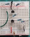
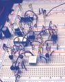
Just as a sanity check in case my schematic doesn't match reality, I've attached an image of my breadboard. The top rail is 5v, the bottom 24v. The green wire is the 5v switch.pnp-switch-24v-0.2-breadboard.jpeg
 
Last edited:

Thread Starter

greycells

Joined Feb 7, 2016
41
Check the voltage on the collector of Q3 with the transistor ON and OFF.
Are the 2 negative rails connected together?
The voltage between GND and Q3 collector is 0v when the LED is off and 23.9 when 0v when the LED is on. The negative rails are definately connected (my new breadboard caught me out earlier because the rails are split half way).
 

sghioto

Joined Dec 31, 2017
8,737
The voltage between GND and Q3 collector is 0v when the LED is off and 23.9 when 0v when the LED is on. The negative rails are definately connected (my new breadboard caught me out earlier because the rails are split half way).
That's not right. The LED should be ON when the Collector of Q3 is 0v and OFF when the collector is 23.9 volts.
 

dl324

Joined Mar 30, 2015
18,447
Is that a pull down on the base? I still have 1.2v when pulling down the base.
The smaller resistance is when things get hot (when the LED is off).
Don't see how that could be the case. Even when the LED is on, dissipation in a 1k resistor would be 6mW.
 
Top