Resistor value when using a PNP to switch 24v from 5v NPN and Schmitt trigger

dl324

Joined Mar 30, 2015
18,448
I understand that resistors in parallel offer less resistance (and in series, more) but I'd have to google the maths!
You add the reciprocals of the resistances and invert the sum:
\( \large R_P=\frac{1}{\frac{1}{R_1}+\frac{1}{R_2}+\frac{1}{R_3}}\)

Two resistors is a special case:
\( \large R_P=\frac{R1*R2}{R1+R2}\)
 

dl324

Joined Mar 30, 2015
18,448
Simulation in LTSpice shows the base pull-up is needed on Q2 to turn the 24v off completely otherwise the leakage current in Q3 can partially turn on Q2, though it is only a few tens of nA.
I thought that might be the case, but I wasn't going to run a simulation. My gut instinct told me it would be required...
 

Thread Starter

greycells

Joined Feb 7, 2016
41
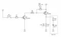
My apologies for messing up the translation from breadboard to schematic - I got the red/green LEDs mixed up so recreated the schematic here while retaining the original component IDs. As per @dl324 & @Irving advice I have added in the pull up resistors on Q1 and Q2 and also a diode to the peeper (there will be one beeper with this and a duplication of this feeding it). This means HC14 is only driving either transistors or a single LED.

Thank you all very much for your help - hopefully this is now done - and I've learnt a lot already.

pnp-debounce-switch-v0.3.png
 

Irving

Joined Jan 30, 2016
5,195
Better, but output labels should point out, as per my schematic above
1674567653882.png


R7 is still unnecessarily small, R1 & R2 too large.

I still don't get the purpose. of this. If the switch is NC then when 5v is turned on the RED LED comes on and beeper sounds. When switch is opened 24v is turned on, RED LED and beeper go off and GREEN LED comes on. What controls the switch? RED & GREEN & Beeper only reflect state of switch, not the 24v so what's the point?
 

Thread Starter

greycells

Joined Feb 7, 2016
41
Better, but output labels should point out, as per my schematic above
View attachment 285936

R7 is still unnecessarily small, R1 & R2 too large.

I still don't get the purpose. of this. If the switch is NC then when 5v is turned on the RED LED comes on and beeper sounds. When switch is opened 24v is turned on, RED LED and beeper go off and GREEN LED comes on. What controls the switch? RED & GREEN & Beeper only reflect state of switch, not the 24v so what's the point?
Thank you Irving

The R7 value is from Denis' reply here: https://forum.allaboutcircuits.com/...v-npn-and-schmitt-trigger.191583/post-1794618 although I'm currently using a 1K for R7 (and a 4.6k for R6). R1 and R2 appear to allow my test LEDs to be pretty bright but I will adjust these when I get the correct bi colour LED (2-2.2v forward voltage for red and 3-3.2v for green).

I hope I haven't messed up the translation but on my breadboard, when the SWITCH_1_NC is (normally) closed, the green light is on and the 24v_SWITCHED_NC_1 is also on. When SWITCH_1_NC is opened, the green light goes out, the red light turns on, the beeper sounds and 24v_SWITCHED_NC_1 is turned off.

This is for a touch sensor - the machine can only move if the 24v_SWITCHED_NC_1 is on - the design intent is that if there's a fault in the 5v or 24v wiring, it fails safe to 'off'). The green (move), red/beeper (stop) are human cues for when the machine is being moved manually.
 
Last edited:

dl324

Joined Mar 30, 2015
18,448
The R7 value is from Denis' reply here: https://forum.allaboutcircuits.com/...v-npn-and-schmitt-trigger.191583/post-1794618 although I'm currently using a 1K for R7 (and a 4.6k for R6). R1 and R2 appear to allow my test LEDs to be pretty bright but I will adjust these when I get the correct bi colour LED (2-2.2v forward voltage for red and 3-3.2v for green).
Using R6=4.6k increases the base current requirement in Q3. You can measure voltages on Q1 Q3 to see if it's saturated.

The circuit might saturate with less than the Ic=10*Ib rule of thumb, but conservative design tells us to use a beta of 10 for 2N2222/2N3906/2N3904. For BC547, a beta of 20 is used. I don't know off hand what it is for 2SC transistors.

I don't know how you can make a statement that R1 and R2 are too large. Brightness depends on the type of LED and purpose. Sometimes very low currents are acceptable.
 
Last edited:

Irving

Joined Jan 30, 2016
5,195
I hope I haven't messed up the translation but on my breadboard, when the SWITCH_1_NC is (normally) closed, the green light is on and the 24v_SWITCHED_NC_1 is also on. When SWITCH_1_NC is opened, the green light goes out, the red light turns on, the beeper sounds and 24v_SWITCHED_NC_1 is turned off.
My bad, I forgot HC14 is inverting so switch closed (input low, output high) puts green/+24 on and red/buzzer off., but that is the reverse of your original (PDF) drawing (I think!).

The R7 value is from Denis' reply here: https://forum.allaboutcircuits.com/...v-npn-and-schmitt-trigger.191583/post-1794618 although I'm currently using a 1K for R7 (and a 4.6k for R6)
Ic(Q3) is a current of approx (24-Vbe(Q2)-Vce_sat(Q3) )/R6 + Vbe(Q2)/R101 = (24-0.6-0.1)/6.8 + 0.6/10 mA = 3.5mA therefore as Ib = Ic/β and β is typically 10 - 20 in saturation, Ib(Q3) = 0.17 - 0.34mA. At these low collector currents β can be much higher.

R7 is (Vout(1Y)-Vbe(Q3))/Ib(Q3) or approx between (4.5 - 0.6)/0.34 kΩ and (4.5 - 0.6)/0.17 kΩ ie 11.5 - 22.9 kΩ, therefore 10k is more reasonable than 820 or 1k. I suspect Denis used the max output current of the HC14 at 4mA and 3.9v giving 975ohm and went for the next standard E12 value below at 820ohm, but there's no need to load the output of the HC14 that much, IMHO.


R1 and R2 appear to allow my test LEDs to be pretty bright but I will adjust these when I get the correct bi colour LED (2-2.2v forward voltage for red and 3-3.2v for green).
For the LEDs, 3 or 4mA is more than enough for a good brightness with modern devices, suggesting R1 (green) is approx (4.5-3.2)/4 kΩ or 325Ω (use 330) and R2 (red) is approx (4.8-2.2)/4 = 650Ω, (use 620 or 680Ω) but as Denis says the existing 1 or so mA may be sufficient. More important is to get a perceived brightness match between the red and green LEDs.

This is for a touch sensor - the machine can only move if the 24v_SWITCHED_NC_1 is on - the design intent is that if there's a fault in the 5v or 24v wiring, it fails safe to 'off'). The green (move), red/beeper (stop) are human cues for when the machine is being moved manually.
Understood, I think, but would it not be more useful to actually monitor the 24v?
 

dl324

Joined Mar 30, 2015
18,448
Actually, I worked backwards from Q2 for the required currents.

If you need more current from the inverters, you could use another inverter in parallel with the existing one. You can only do this with devices in the same package.

If you didn't have spare inverters in the package, you could switch to 74AC14.
 

Thread Starter

greycells

Joined Feb 7, 2016
41
My bad, I forgot HC14 is inverting so switch closed (input low, output high) puts green/+24 on and red/buzzer off., but that is the reverse of your original (PDF) drawing (I think!).
My bad I think - I mis-translated the breadboard to schematic on the first drawing! Good start, eh?

Ic(Q3) is a current of approx (24-Vbe(Q2)-Vce_sat(Q3) )/R6 + Vbe(Q2)/R101 = (24-0.6-0.1)/6.8 + 0.6/10 mA = 3.5mA therefore as Ib = Ic/β and β is typically 10 - 20 in saturation, Ib(Q3) = 0.17 - 0.34mA. At these low collector currents β can be much higher.

R7 is (Vout(1Y)-Vbe(Q3))/Ib(Q3) or approx between (4.5 - 0.6)/0.34 kΩ and (4.5 - 0.6)/0.17 kΩ ie 11.5 - 22.9 kΩ, therefore 10k is more reasonable than 820 or 1k. I suspect Denis used the max output current of the HC14 at 4mA and 3.9v giving 975ohm and went for the next standard E12 value below at 820ohm, but there's no need to load the output of the HC14 that much, IMHO.
So the lower the resistance into the base of Q3, the greater the load (current drawn?) from the HC14?

For the LEDs, 3 or 4mA is more than enough for a good brightness with modern devices, suggesting R1 (green) is approx (4.5-3.2)/4 kΩ or 325Ω (use 330) and R2 (red) is approx (4.8-2.2)/4 = 650Ω, (use 620 or 680Ω) but as Denis says the existing 1 or so mA may be sufficient. More important is to get a perceived brightness match between the red and green LEDs.
That was my plan - just to get the LEDs reasonably bright but matching in intensity.

Understood, I think, but would it not be more useful to actually monitor the 24v?
The system has a 24v supply that feeds into a number of connections on the controller PCB - based on whether the voltage is high (a switch is closed) or low (the switch is open) then the controller PCB will take/allow actions. But I need to be able to do the debouncing and human cues so can't just use the triggering switch directly (the switch that feeds into SWITCH_1_NC).

But now I'm somewhat confused. During testing with 3.3/5v, I had an LED between pin 3 on Q2 and GND which turned off as expected when SWITCH_1_NC was opened - however now I have built the 24v regulator onto the breadboard I can obviously not use an LED as a test indicator so I put the multimeter between between pin 3 on Q2 and GND - this reads 24v (as expected) when SWITCH_1_NC is closed but *still* reads 24v when SWITCH_1_NC is opened. Al the other functionality works as expected.

Am I missing something fundamental here? I thought Q2 would allow/deny 24v current flow acting like a switch (or relay) - it seems to do this for the LED but not for a meter reading.

This is a very rough layout of the system:

Screenshot from 2023-01-24 18-25-14.png
 

Irving

Joined Jan 30, 2016
5,195
That's because there's some leakage through Q1, the meter only needs a few uA. With the 24v OFF measure the current from Q1 collector to ground..,. it should be no more than a few uA. If its more then its not being turned off fully. Be careful not to do his with the 24v switched on, you could blow the fuse in the meter if the PSU has any grunt, though Q1 will limit the short circuit current to some extent..

To use a LED on 24v use a 4k7 - 10k resistor in series.
 

Thread Starter

greycells

Joined Feb 7, 2016
41
That's because there's some leakage through Q1, the meter only needs a few uA. With the 24v OFF measure the current from Q1 collector to ground..,. it should be no more than a few uA. If its more then its not being turned off fully. Be careful not to do his with the 24v switched on, you could blow the fuse in the meter if the PSU has any grunt, though Q1 will limit the short circuit current to some extent..

To use a LED on 24v use a 4k7 - 10k resistor in series.
Ah, so I need a kinda 'pull down' on Q1 collector to make it drop - presumably the 25mA of my controller PCB will be sufficient? (I haven't dared connect my breadboard to it!)
 

Irving

Joined Jan 30, 2016
5,195
Depending on how closely matching means, it might not be easy to do with LEDs of different colors and different color sensitivity in people.
True. If your phone camera can be set to B&W view the 2 LED that way to get common light intensity. Thats probably the best u can do.
 

Thread Starter

greycells

Joined Feb 7, 2016
41
After a frustrating couple of days (primarily caused by a very old & very dodgy breadboard - and a (feeling) very old & dodgy human), I've isolated the part of the circuit that is giving me trouble. As suggested by @sghioto, I put a 22k resistor (R102) between collector and GND of Q2 but only by reducing it further to 4.7k did the LED turn off. However there is still 1.2v across the resistor when the LED is off but if I reduce the value any further, the resistor gets very hot.
Post Covid brain fog (one of the reason I'm trying to learn this) is not helping but I feel like I've missed something. I kinda expected to be able to get the 24v to turn off completely without a very hot resistor? Also, it might well be that my control card will pull sufficiently to ground to negate this resistor.
I've checked Q3 across various combinations of junctions and that appears to have either 0v or 5v as expected.
pnp-switch-24v-v0.2.png
 

Irving

Joined Jan 30, 2016
5,195
1.2v across 4k7 = ~250uA which isn't unlikely if Q3 not turning off fully. Try a 10k from base of Q3 to ground to make sure no noise (mains hum etc) is turning it partly on when the base is disconnected.
 
Top