resistance temperature detector (RTD)

Thread Starter

mussa

Joined Jun 10, 2019
45
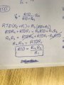
The resistance temperature detector (RTD) forms one arm of the Wheatstone bridge as shown in the figure below the RTD has a resistance of
at temperature of
in formula
,
is the temperature coefficient of RTD in thermal equilibrium with the measuring temperature.

1. Determine the measuring temperature of RTD when the bridge is balanced.

2. Determine the output of voltage in the operational amplifier at temperature
.
 

ericgibbs

Joined Jan 29, 2010
18,872
hi mussa,
Welcome to AAC.
As this is homework, please post your attempt at answering, we can then guide you through the project.
E
 

ericgibbs

Joined Jan 29, 2010
18,872
hi,
Have you calculated the RTD resistance at 300C.?
Use the formula in the question notes.
E
Update:
Who drew the circuit diagram.?
 
Last edited:

ericgibbs

Joined Jan 29, 2010
18,872
hi,
Q1 does not make much sense.?
Consider if I chose 0C to be the balance temperature, I would adjust VR1 until the Vout =0V
If I said I chose 25C, I would adjust VR1 for Vout=0V.

Does the tutor realise that as the RTD resistance increases with temperature, the Vout is driven negatively.?
So the the OPA must have dual supply voltages.

If a single supply voltage is used the INV and Non INV inputs to the OPA should be changed over.

E

EDIT:
Added a LTSpice simulation to show the results.

RTD1.PNG
 

Thread Starter

mussa

Joined Jun 10, 2019
45
my bad i missed this part (the value of the variable resistance R1 must be set to 41.485 ohm to balance the bridge circuit
 

Thread Starter

mussa

Joined Jun 10, 2019
45
from this i can say RTD is
hi,
Q1 does not make much sense.?
Consider if I chose 0C to be the balance temperature, I would adjust VR1 until the Vout =0V
If I said I chose 25C, I would adjust VR1 for Vout=0V.

Does the tutor realise that as the RTD resistance increases with temperature, the Vout is driven negatively.?
So the the OPA must have dual supply voltages.

If a single supply voltage is used the INV and Non INV inputs to the OPA should be changed over.

E

EDIT:
Added a LTSpice simulation to show the results.

View attachment 180196
the question gave or set R1 to be 41.485 ohm which doesn't matter as u say, bic no matter what the value of R1 be the the temperature of RTD for the balanced bridge will remain 0. In case we set R1 to be 41.485 oh, our RTD will also be 41.485 ohm. I'm i correct?
 

ericgibbs

Joined Jan 29, 2010
18,872
hi,
If VR1 was stated as set to 41.85R then for a Vout=0 the RTD would have to be 41.85R.
What do you calculate the Temperature to be when the RTD is 41.85R.??
E
 

ericgibbs

Joined Jan 29, 2010
18,872
hi,
How can that be correct, when the question states RTD= 25R at 0C.??
It must be hotter than 0C.
45.85= 25(1+(0.003925*temp)).....
E
 

Thread Starter

mussa

Joined Jun 10, 2019
45
hi,
How can that be correct, when the question states RTD= 25R at 0C.??
It must be hotter than 0C.
45.85= 25(1+(0.003925*temp)).....
E
I see, RTD's temperature is 209C, then for question 2 at temperature of 300C RTD is 54 ohm to find the output voltage at that temperature what shall i do?
 

ericgibbs

Joined Jan 29, 2010
18,872
hi,
Sorry I made a typing error
45.85= 25(1+(0.003925*temp))..... that should be 41.85R, so recalculate the value.

To calculate Vout, calculate the Gain of the OPA amplifier, do you know how to do that.?
E
 

Thread Starter

mussa

Joined Jun 10, 2019
45
hi,
Sorry I made a typing error
45.85= 25(1+(0.003925*temp))..... that should be 41.85R, so recalculate the value.

To calculate Vout, calculate the Gain of the OPA amplifier, do you know how to do that.?
E
its 41.485 = 25(1+0.003925*t)) = 168C
i know gain is output/input voltage, but in this we are asked to find output voltage?
 

ericgibbs

Joined Jan 29, 2010
18,872
hi.
You can use this equation for bridge, see image.

The way the question is written does not make sense to me.

If the bridge is being use to measure temperature, the RTD would be 25R at 0C, the RV1 trimmer would be set to give 0V output from the bridge.

If you the heated the RTD to say 168C, the RTD would have a resistance of 41.485R.

You would then use the equation with those values to find the bridge Vout.

E
 

ericgibbs

Joined Jan 29, 2010
18,872
hi,
If you look at the plots in post #10, you will see that the OPA amp saturates at -12V at approx 140C.

It is also a negative going output, which means the OPA must have dual supplies.

My advice would be to go back to your tutor and ask for a better worded question and an OPA amplifier design that works for the questions.

E
 

Thread Starter

mussa

Joined Jun 10, 2019
45
hi,
If you look at the plots in post #10, you will see that the OPA amp saturates at -12V at approx 140C.

It is also a negative going output, which means the OPA must have dual supplies.

My advice would be to go back to your tutor and ask for a better worded question and an OPA amplifier design that works for the questions.

E
will do that thanks a lot
 
Top