Request for input/criticisms

Thread Starter

Michael Gronlund

Joined Feb 3, 2018
9
Hello All,

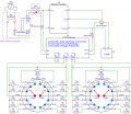
I'm just starting to get into building circuits primarily with Arduinos as an MCU. However I decided I need (want) a bench power supply, and thought it would be a good first major project (major for me). The AC/DC power supply will put out 24V/10A. I wanted to have an option to various lower voltages (3.3v, 5v, 9v, 12v) at 5A on isolated circuits. I wanted to use a switch with an LED rated at 12VDC to turn the individual voltages on and off. Attached is a schematic I came up with which should provided 5V/5A using an 4N25 optocoupler and TIP120 to power a LM1084IT to regulate the 24V power source to what I want.

This my first schematic I've designed from scratch, and wanted to see if anyone would provided any input/criticisms. (Please be gentle :/ )

Schematic_Prototyping_Cropped.png
 

Thread Starter

Michael Gronlund

Joined Feb 3, 2018
9
AlbertHall asked a good question..
What makes the switch rated for 12v volts?
Is it a solid state switch? Mechanical switch with Led? If the limitation is the LED, you could add an external resistor to adjust the current limit at 24V, eliminating U2 and Q1.

eT
I'm guessing it's the LED in the switch.

So something like this?

Schematic_Prototyping_Cropped2.png
 

Thread Starter

Michael Gronlund

Joined Feb 3, 2018
9
Something is wrong with the location of R3 & R4.
Using 24 volts for the input voltage will likely limit the output current to much less than 5 amps because of the high power dissipation.
The amperage is the reason I originally had it going through the isolation of the TIP120 (Which on hindsight should be a TIP14x as the TIP120 is rated at 3A).

But if I am grasping voltage dividers correctly R3 & R4 should limit the voltage to 12V for SW1, although I'd have to use multiple resistors or large wattage resistors to get the 25W supply at the load.

Is my understanding / math flawed somehow?
 

eetech00

Joined Jun 8, 2013
3,961
I'm guessing it's the LED in the switch.

So something like this?
Like this....
But you need to measure (or look at switch spec) the current thru the LED at 12v so you can calculate the size Rext should be at 24v, to maintain the same current. In the example below I've shown an LED that draws 20mA with a 2V drop.

I've also shown a fixed output version of the regulator instead of the adjustable.

But it would be operating almost at the input voltage max limit (25V).


upload_2019-7-9_20-7-32.png

An LM338 would be a better fit.

upload_2019-7-9_20-40-50.png
 
Last edited:

ronv

Joined Nov 12, 2008
3,770
The amperage is the reason I originally had it going through the isolation of the TIP120 (Which on hindsight should be a TIP14x as the TIP120 is rated at 3A).

But if I am grasping voltage dividers correctly R3 & R4 should limit the voltage to 12V for SW1, although I'd have to use multiple resistors or large wattage resistors to get the 25W supply at the load.

Is my understanding / math flawed somehow?
It's just a waste of power.
Have you considered building or buying a buck converter?
https://www.ebay.com/itm/XL4015-5A-...=142968844998397cc5e9f83f460db7828e54ec480c8b
 

Thread Starter

Michael Gronlund

Joined Feb 3, 2018
9
Like this....
But you need to measure (or look at switch spec) the current thru the LED at 12v so you can calculate the size Rext should be at 24v, to maintain the same current. In the example below I've shown an LED that draws 20mA with a 2V drop.

I've also shown a fixed output version of the regulator instead of the adjustable.

But it would be operating almost at the input voltage max limit (25V).


View attachment 181368

An LM338 would be a better fit.

View attachment 181370
Thank you everyone for your responses!

First I apologize for the delay in my response (been a bit busy), and second I appreciate the detail in your response.

I'll have to wait until I get the switches to see what the ratings are on it, but I like your minimalistic approach.

Input voltage would be 24v. The LM338 is one of pieces I couldn't find. I used the LM1084IT in lieu of it.

Just curious if my original schematic would actually work. Did I at least have a basic grasp of what I was attempting?
 

Thread Starter

Michael Gronlund

Joined Feb 3, 2018
9
So this is what I think I'm going to do.

eetech00's responses made me realize that I was over complicating things in my own head (as I often do) trying to give myself more power options than I would ever use at once. In reality I don't see myself using more than two different volts at once. One for logic level at 3-5v and one for load at 9-24v. So I decided the best option would be to use some off the shelf components as ronv suggested like a AC/DC power supply, LTC3780 module, ammeter/voltmeter and give myself two voltages to work with. On the LTC3780 module, remove the on board pot and wire in a rotary switch so I can use preselected voltages of 3/5/9/12/24 VDC and currents of 100/200/500/750/1000ma and on both have an option to use panel mounted potentiometers to dial-in other values.

I still need to work out the math for the resistor values for the voltage dividers off the rotary switches but I think I have a good working idea in theory.

The LTC3780 module can deliver up to 30VDC @ 10A (With additional heat sinking) and the ammeter can measure up to 100VDC and 10A. The shunt resistor is rated at 10A.

Attached is an image of the LTC3780 module and ammeter/voltmeter (I'll use two of each). 4xDP6T rotary switches, 2x200kΩ panel pots, 2x500kΩ panel pots.

On the schematic everything after the switching power supply would be duplicated to give me the second voltage/current options.

Just FWIW I choose this version of the LTC3780 module because of the under voltage protection which I may need/use if I decide to make the power supply portable for some reason and run off an automotive battery or 18650 array (for example).
 

Attachments

Last edited:
Top