Circuit request: Driving a security LED in a car with a 0.00 - 0.65 volt input range

Thread Starter

darksol

Joined Nov 8, 2017
11
Greetings!

So over at Lotustalk.com a gentleman has come up with a digital LCD gauge cluster that replaces the stock analog one for the 2000+ Lotus Elise range:
http://www.lotustalk.com/forums/f259/elise-lcd-dash-356313/

The issue I'm having is that the stock cluster has a alarm/security LED input (from the Cobra 8186 alarm) that issues a 0.00 -> 0.65 volt signal (according to my Fluke 72 DMM) that flashes an LED to signify the alarm is on and the car is immobilized.

There is no LED supplied with the new gauge cluster. Without that LED you have no idea if the car's alarm has been set and I don't want to find out by opening the door and the siren going off every time... It's certainly nice to see the light stop flashing when I press the button on the fob. :)

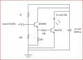
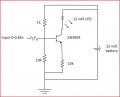
So I'd like some suggestions on a low current draw circuit that drives a plain ole' red LED using a 0.00 (off) to 0.65 (on) volt input range...

Of course since it's in the car there is 10.0 - 13.2 volt battery input available (dependent if the battery is low or the alternator is charging) for the circuit.

Thanks in advance!
 

Attachments

Thread Starter

darksol

Joined Nov 8, 2017
11
Ok after doing some research (what a WONDERFUL site!) I think that this may work...

I have a 12 volt LED that already has an inline current limiting resistor so I used that in this schematic.

Can someone please confirm if this will work? - thanks!
 

Attachments

Thread Starter

darksol

Joined Nov 8, 2017
11
Ooops - didn't need the 10k resistor to ground or the LED would never have enough current to light up... :)
willthiswork2.JPG
 

Thread Starter

darksol

Joined Nov 8, 2017
11
I cannot find a way to edit/tweak posts I've already made - so this is a learning process... :)

This should work perfectly - it does with the http://www.falstad.com/circuit/ simulator!

upload_2017-11-8_13-44-45.png

--- cut here ---

$ 1 0.000005 0.04168620196785084 67 2 50
172 240 256 192 256 0 6 0.68 0.68 0 0 0.5 B7 Voltage
t 304 256 352 256 0 1 -2.2603235364670473 0.6566549224643871 100
r 352 144 352 192 0 680
g 352 272 352 352 0
162 352 192 352 240 1 2.1024259 1 0 0 0.01
R 352 144 352 112 0 0 40 12 0 0 0.5
r 240 256 304 256 0 220

--- cut here ---
 

jasone

Joined Nov 2, 2015
50
To clarify to have a 0V-0.65V square wave signal out of the Cobra alarm module that flashes an LED on the old dash assembly correct?

Im not sure why you need the 220ohm resistor.
 

Thread Starter

darksol

Joined Nov 8, 2017
11
To clarify to have a 0V-0.65V square wave signal out of the Cobra alarm module that flashes an LED on the old dash assembly correct?

Im not sure why you need the 220ohm resistor.
Jason, absolutely correct!

I tossed the 220 ohm resistor in just in case there was too much current being drawn from the alarm but I suppose I could just leave it out.

Been a long time since I wired anything like this. I've forgotten 95% of all my electronic knowledge from grade school in the early 1970's :)

-David
 

jasone

Joined Nov 2, 2015
50
Jason, absolutely correct!

I tossed the 220 ohm resistor in just in case there was too much current being drawn from the alarm but I suppose I could just leave it out.

Been a long time since I wired anything like this. I've forgotten 95% of all my electronic knowledge from grade school in the early 1970's :)

-David
Im sorry for your loss haha. The biggest struggle I face in my technical carrier is retaining all the information I attempt to remember...I mean learn....I mean understand. I read an interesting article the other day titled "If I wanted to study this hard, Id have gone to real college." My simple brain feels like its in a constant state of training and subject refreshment.

Good luck on this project.

-Jason
 

Thread Starter

darksol

Joined Nov 8, 2017
11
Open collector? Well that's certainly a possibility.

It certainly triggers the LED at a lower voltage that the other circuit does (+0.22 volts)...

upload_2017-11-9_2-45-8.png

--- cut here ---
$ 1 0.000005 0.04168620196785084 67 2 50
172 240 256 192 256 0 6 0.22440000000000001 0.68 0 0 0.5 B7 Voltage
t 304 256 352 256 0 1 -6.519097451754346 0.6341643387374681 100
r 352 144 352 192 0 680
g 352 272 352 352 0
162 352 192 352 240 1 2.1024259 1 0 0 0.01
R 352 144 352 112 0 0 40 12 0 0 0.5
d 304 256 240 256 1 0.805904783
r 304 144 304 192 0 22000
w 352 144 304 144 0
w 304 192 304 256 0
--- cut here ---
 

Thread Starter

darksol

Joined Nov 8, 2017
11
OMG - just close the thread :)

Confirmed - It's open collector.

I connected the + of the (12v) LED to +12v of the battery and the - to the alarm signal... and it flashes as it should.

upload_2017-11-9_4-22-50.png

#doh #smh
 

Bordodynov

Joined May 20, 2015
3,430
Notice that in my circuit, I did not use a conventional diode, but a Schottky diode. With a conventional diode, the transistor will not fully shut down. The LED will not completely go out.
 

Thread Starter

darksol

Joined Nov 8, 2017
11
Notice that in my circuit, I did not use a conventional diode, but a Schottky diode. With a conventional diode, the transistor will not fully shut down. The LED will not completely go out.
I did notice that. I will remember this solution in the future if I need it. Thanks!
 

jasone

Joined Nov 2, 2015
50
Good job philba.

Darksol do you have a power probe? I use my power probe 4 more than my DVOM on cars. Its a lot faster and easier to handle. You likely would have seen the circuit pulse to ground visually via the little green light and sound rather than focus on the 0.6V.
 

Thread Starter

darksol

Joined Nov 8, 2017
11
Good job philba.

Darksol do you have a power probe? I use my power probe 4 more than my DVOM on cars. Its a lot faster and easier to handle. You likely would have seen the circuit pulse to ground visually via the little green light and sound rather than focus on the 0.6V.
I do not have a power probe - perhaps it should be something I add to my Xmas list :)

Do you have any recommendations?
 

philba

Joined Aug 17, 2017
959
Glad you got it sorted out. Retrofitting electronics has always been a very quirky and confusing thing for me. Bang your head against the wall for ever and then a fresh pair of eyes does the trick in like 2 seconds. Keeps me humble!
 
Top