 Facebook
 Google
 GitHub
 Linkedin
Hello,
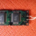
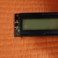
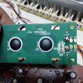
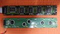
Im trying to change a 4002 display of my synth.
The old one has 7 pins (2 more on the other side for the backlight with a small thin white cable to connect)
The new one has 8 pins and the pin 15-16 are the backlights.
How can I connect the little white cable to the new display? I weld to the pin 15-16 or the other side which says A2-A1-K2-K1
Thank you very much
Attachments
-
 1.6 MB Views: 3


") )
)


