Facebook
 Google
 GitHub
 Linkedin
Hello,
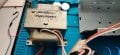
I recently started to attempt to figure out what is wrong with an old fridge that I need to get working (Norcold DE-251E) and it appears that the DC circuit side of the inverter failed, this board outputs power to the 23vac compressor.
Typically this board has two main functions, take 120vac and output it to 23vac to compressor and the other is to take 12vdc and output to 23 vac. The transformer is 7 legged, 2 for 120vac input, 3 for 12-0-12vdc input, and 2 for 23vac output.
The board also no manages the evaporator thermistor, condenser thermistor, and the temperature control sensor.
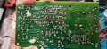
Currently I have the board / transformer off for testing purposes and have observed that 120vac passes properly but 12vdc is not.
I observed that the relays are properly functioning but at the output of the alternating 12vdc there is only +12vdc on the center leg, which implies the failure is with the oscillating circuit.
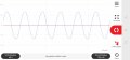
My electronic knowledge is on and off as I did study circuit design but it's become more of a hobby than my career so while I could figure out an alternative circuit to produce (research and copy) a true sine (does it really need to be a true sine??) at 12-0-12 from a 12vdc input, preferably I repair the original circuit.
Any ideas??
Thanks,
--Phil
I recently started to attempt to figure out what is wrong with an old fridge that I need to get working (Norcold DE-251E) and it appears that the DC circuit side of the inverter failed, this board outputs power to the 23vac compressor.
Typically this board has two main functions, take 120vac and output it to 23vac to compressor and the other is to take 12vdc and output to 23 vac. The transformer is 7 legged, 2 for 120vac input, 3 for 12-0-12vdc input, and 2 for 23vac output.
The board also no manages the evaporator thermistor, condenser thermistor, and the temperature control sensor.
Currently I have the board / transformer off for testing purposes and have observed that 120vac passes properly but 12vdc is not.
I observed that the relays are properly functioning but at the output of the alternating 12vdc there is only +12vdc on the center leg, which implies the failure is with the oscillating circuit.
My electronic knowledge is on and off as I did study circuit design but it's become more of a hobby than my career so while I could figure out an alternative circuit to produce (research and copy) a true sine (does it really need to be a true sine??) at 12-0-12 from a 12vdc input, preferably I repair the original circuit.
Any ideas??
Thanks,
--Phil
Attachments
-
 2.1 MB Views: 22
 -
 784.4 KB Views: 22
 -
 2.2 MB Views: 23
 -
 379.2 KB Views: 23
 -
 1,017.3 KB Views: 27