Please look at the picture attached. The relay on the left has some info printed on the bottom right
about 5A 250AC and 5A 30VDC. Can someone shed some light on it please.
If the load says 24vac then this has to be the nature of the supply, so it sounds like you could be wrong with 24VDC? How do you know the nature of the solenoid if not present?
How come your boss gave you this task?
Max.
It was my first day on a new job and I dont know why he gave me such a task. I ask for the circuit diagrams which they said there was'nt one.
It was too hard because I had no idea what the load device was.
It was my first day on a new job and I dont know why he gave me such a task. I ask for the circuit diagrams which they said there was'nt one.
It was too hard because I had no idea what the load device was.
Sounds like a challenge, especially for a first day, maybe a bit of a test!
What you should do if possible is trace the supply wire from the relay back to the source if possible and this should tell you alot, unless he has not implemented a supply at all yet.
Is this an existing previously working system?
Max.
So far you've gotten good answers. The problem has been in your understanding of what things mean. Let me take a slightly different approach; maybe this will clear it up for you.
A relay consists of two distinct parts. First, there's the switch, the C (common), the NC (normally closed) and the ON (normally open) portions of that switch. The second part of the relay is the coil. ALL the coil does is either throw the switch from the NC to the NO - or not. When you energize the coil it will switch from C - NC to C - NO (moving the contact between the common and the normally closed switch from that position to the other, the normally open)
The coil is rated in its own voltage - be it AC or DC, be it 120 volts or 12 volts or 5 or 3 or some other voltage - depending on what the relay was designed to use as a control voltage. Other than that the coil does nothing more. No rectification, no addition or subtraction to the contacts.
The switch (the contacts) is simply a switch. Like any switch, it's going to be rated to handle certain loads. So the switch (the coil you have) can handle switching up to 5 amps on 120 volts AC (NOT DC). OR it can switch up to 5 amps on 30 volts DC. That's the maximum rating of the switch.
So if you're planning on controlling a circuit with 12 volts DC but not drawing more than 5 amps then the switch can handle the load. However, if you're going to be attempting to switch more than 5 amps - the switch will not handle the load. The contacts can pit and burn out or can weld shut, rendering the relay useless.
Same is true if you're using a low voltage to control a much higher voltage. Suppose you're using an Arduino. It runs on about 5 volts. A coil rated for 5 volts DC will be needed. The switch (whatever its rated for) can handle (in the case of your relay switch rating) 120 volts AC and up to 5 amps.
You can use different voltages to control different voltages. However, the relay does not condition or change in any way the sources you're using the switch to control.
Your relay can't handle switching more than 5 amps. Period! If you're using 120 volts AC - you're fine to switch 5 amps. But if you want to switch - oh, lets say 48 volts DC - at 5 amps - your relay can't be expected to live very long because you're over the capacity of the switch rating.
If I'm reading your relay correctly, the coil is controlled by 230 VAC (not DC).
Thanks Tony for Shedding more light on this topic. You've also been of great help. The relay picture I posted is not the actual one in
the control panel I stated before but it's the labelling on the case of Ac and DC that confused me. As long as DC or AC loads can be connected
to the output regardless of the AC input, then I have got it.
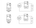
Perhaps this drawing will help. Let me explain a little about it:
You see one relay in each of its conditions (de-energized and energized). Note the position of the switch. The dashed line is sometimes used to indicate the coil actuating the switch. In the de-energized position the C and the NC contacts are directly connected by the switch. When energized, the switch changes position and the normally open switch becomes closed.
The two circuits represent the max capability of the switch in either condition - AC or DC. You don't have to have 30 VDC or 120 VAC being switched, it's just the MAX rating. You can switch 48 volts AC (Alternating Current) up to 5 amps. You could have 10 volts (AC or DC) up to 5 amps.
All the relay does is takes a controlling voltage and uses it to control a different voltage. And in many cases it can also control the same exact voltage. There's no law that says a relay must control a different voltage. Look at your car. There's a fuel pump relay - uses 12 volts to control a 12 volt pump. There's a horn relay - uses 12 volts to control a 12 volt horn. And many more examples. So why use a relay to control the same voltage? In the car you tap the horn button. It sends 12 volts at a very low current to the relay and the relay controls the heavier load. Car relays typically control up to 40 amps. That's because the switch is rated to handle that much current. Otherwise the horn button on your steering wheel would have to be much heavier and more robust. And if it fails you have a whole lot of other things to deal with just to fix the horn button. With a relay under the hood it's very unlikely the horn button will ever go bad. If any part of it fails it's much more likely to be the horn relay - and that's just a quick swap. No need to rip the steering wheel apart.
The computer controls the fuel pump. IF the computer had to supply 20 amps to the pump then the computer would be quite heavy and have to deal with a lot more power. But with a relay the computer can send a 12 volt signal to the relay, which may draw 200 mA (milli-amps, or 0.2 amps). The computer is much smaller and has much less work to do.
Your control panel obviously (if I read the relay correctly) runs on 230 volts. Maybe on 220, I don't know for sure. The relay could be controlling a circulating pump that runs on 120 volts and draws 2 amps (not milli-amps). The relay is well suited for this sort of control. And a switch that is rated for 230 volts may have to supply 60 mA to the relay in order to control the heavier current. (the 120 volt 2 amp pump motor). Maybe the pump runs on 230 volts. I don't know. The point is - the relay controls power to the load. If the load exceeds the relay's rating then it will burn the contacts.
Sounds like a challenge, especially for a first day, maybe a bit of a test!
What you should do if possible is trace the supply wire from the relay back to the source if possible and this should tell you alot, unless he has not implemented a supply at all yet.
Is this an existing previously working system?
Max.
Yes. It is a Big Machine used in a bakery for washing Trays. It seems to be obsolete because I went to the manufacturers website
and couldn't find the machine or documents related to it. The machine is in working order.
I had a baptism of fire on my first day.
So what happened to the solenoid and where was the M/C made? UK?
Older machines tended to use ac (240vac?) , as I mentioned if the machine was working I would assume the solenoid supply to the relay is still intact, if so it should be possible to trace this conductor back to the source, fuse etc, and detect the nature of the supply.
That would be my first thing if I were set the same task.
Max.
You can see in the picture a tap with nothing on top. I had to workout what had to go on top. There was 3 of them. Ill post photos later. I'm looking for the machine manufacturers. I think it's in Holland. The control panel picture shows the solenoid in the right hand corner I traced the wire to.
I told my boss it may be an actuator needed to turn the tap on or Solenoid. He agreed it is a solenoid.
It appears the solenoid coils are missing for some reason!!?
What I would tend to do is spec in another solenoid valve with the same capacity, it appears to be controlled by a PLC, and a rats nest of wiring that has most likely been changed over time.
I don't see much evidence of DC supplies so although Europe went to the practice of DC solenoids much sooner than N.A. I would guess they were AC type.
Where is the original supply conductors to the solenoid valves?
Looks a prime candidate for a retro-fit!
Max.
Looking at that rat's nest, I'd advise the boss hire a professional. Chances for serious personal injury are definitely high. And there are good chances you could end up blowing something out - or up. Or burning the facility down.
Cheap is not the way to go on this. The cost of a professional who is licensed and insured is the best way to go.
Out of interest, what is the make/model of the PLC? (top of the cabinet) In the pic it is showing inputs and outputs active, so it must be running?
Max.
I told him it will be PLC controlled. All the other taps on the machine had the same problem so there was nothing to refer to.
Look at the picture, divide it into 4 and look at the bottom right section towards the top.You can also barely see the conductor hanging (whitish or grey ) with a black plastic terminal cover. That is partially the top of the machine I had to climb onto using a ladder. You can see 3 taps with nothing on them.
Incidentally how is it working with solenoid valves missing?
In your last photo I see the (square black) connector hanging, trace where these wires go back to>
Max.
Incidentally how is it working with solenoid valves missing?
In your last photo I see the (square black) connector hanging, trace where these wires go back to>
Max.
I had mentioned they appeared active, I use Mitsubishi, what model is it, this brings up another issue, if you don't have a copy of the PLC ladder then if the PLC dies or loses memory the machine is dead, especially if the OEM is no longer around.
You need to trace the other relay contact back to the panel to find out how it is fed.
Max.
 Facebook
 Google
 GitHub
 Linkedin
")