 Facebook
 Google
 GitHub
 Linkedin
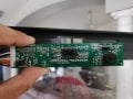
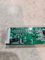
I know you're looking at other things, but does the compressor have a start capacitor? In my experience that's the primary cause of failure in refrigerant-based coolers. I keep a spare for my A/C on hand.Yes it does have compressor. It is 10 years old....
Relay chatter/sparking
- Thread starter Macknumber9
- Start date
| Thread starter | Similar threads | Forum | Replies | Date |
|---|---|---|---|---|
| B | Relay Chatter but not all the time | General Electronics Chat | 2 | |
| C | LDR circuit causing Relay chatter | Sensor Design & Implementation | 2 | |
| H | Relay chatter circuit | General Electronics Chat | 1 | |
|
|
Differential Controller Relay chatter | General Electronics Chat | 13 | |
|
|
Output to relay causing chatter. | General Electronics Chat | 12 |


