Relay chatter/sparking

Thread Starter

Macknumber9

Joined Jun 10, 2023
34
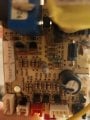
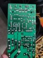
Picked up a free wine cooler...diagnosed a bad relay on pcb...I was getting 12vdc on power supply side of coil but only 6vdc on the side driven by the transistor....I was thinking I shouldn't see 6vdc...I'm confused though not sure if when probing ground to coil I should see 12vdc or 0vdc there...anyways I turned off the machine and jumped 12 volts to the supply side and grounded the other side (transistor side) and got the relay to click but did not have continuity on the load contacts....so I figured bad relay....well I was right because I soldered in new relay and it fired up...thought all was well until I heard a terrible rattling sound...checked the relay and it was dark in the room and there's a tiny little slit in the top of the relay...I could see sparks flying in there....is this relay chatter?

Now I was thinking it could possibly be a compressor that is going bad and drawing too much amperage....but that doesn't explain the odd 6vdc on the transistor drive side of the coil....or does it?

Could it be bad compressor? If so how would I test? Just test the amperage coming out of it?

Bad transistor?

Diode?

Possibly the transistor is bad or something is going wrong on the ground side of this coil causing a weak electromagnetic field and not allowing a strong pull on the contacts?
 

wayneh

Joined Sep 9, 2010
17,505
Could it be bad compressor?
Most wine coolers don't have compressors but instead use thermoelectric cooling. It still takes a lot of current, but no moving parts or refrigerant. There's a long thread on this site addressing common problems with such appliances.

But, since you obviously have a relay switching a big current, maybe your unit is indeed a refrigerant-based model.
 

Thread Starter

Macknumber9

Joined Jun 10, 2023
34
Most wine coolers don't have compressors but instead use thermoelectric cooling. It still takes a lot of current, but no moving parts or refrigerant. There's a long thread on this site addressing common problems with such appliances.

But, since you obviously have a relay switching a big current, maybe your unit is indeed a refrigerant-based model.
Yes it does have compressor. It is 10 years old....

Just did another test....I still am getting 12vdc on supply side of coil which is normal but on the opposite side I am only getting 6vdc which is not good. Definitely dealing with a low voltage coil here....now I just need help diagnosing the issue....the test I just did was base transistor voltage...the base transistor voltage is only .5v which is supposed to be .7v....

Now is this low voltage anyway related to an internal problem with the transistor itself or would this lead towards whatever is responsible for supplying this voltage to the base to activate the transistor?
 

Pyrex

Joined Feb 16, 2022
315
...jumped 12 volts to the supply side and grounded the other side (transistor side) and got the relay to click but did not have continuity on the load contacts....so I figured bad relay....well I was right because I soldered in new relay and it fired up...thought all was well until I heard a terrible rattling sound...checked the relay and it was dark in the room and there's a tiny little slit in the top of the relay...I could see sparks flying in there....is this relay chatter?

Now I was thinking it could possibly be a compressor that is going bad and drawing too much amperage....but that doesn't explain the odd 6vdc on the transistor drive side of the coil....or does it?
i suspect something wrong with power supply. When the relay is actuated, the compressor starts and takes a lot of current at start moment. If receptacle in the wall is not OK , or a contact on the PCB is not OK,or motor start circuit is not OK, then voltage decreases significantly and the relay rattles. Relay contact weares very intensive. This explains the relay fault. And flying sparks inside, too. If the cooler is OK,the relay starts instantly, and no chattering nor rattling occurs
 

Poyntat

Joined May 24, 2022
60
Replace the relay drive transistor, check for dry joints around the pcb area near the relay, drive transistor, relay suppression diode.
What drives the transistor?
 

Thread Starter

Macknumber9

Joined Jun 10, 2023
34
Replace the relay drive transistor, check for dry joints around the pcb area near the relay, drive transistor, relay suppression diode.
What drives the transistor?
There is a 6 pin wire harness...on that 6 pin wire harness the pin labeled "comp" for compressor drives the transistor base voltage....it comes down to a resistor and then through a small 104 capacitor...

Between the relay coils there is a diode...

I attached a pic
 

Attachments

Poyntat

Joined May 24, 2022
60
Ok, unfortunately the image is not much help other than to confirm that the pcb is of the usual quality
for this type of appliance.
If you are sure that there are no poor solder joints after doing a visual check and probing around the pcb with a non- conductive tool (suitable piece of wooden dowel), with the pcb powered, then going back to the voltages around the relay drive transistor, what is the voltage on the drive wire from the six pin connector/ harness before the transistor base resistor?
Also, what is the make/model of your free cooler?
 

Thread Starter

Macknumber9

Joined Jun 10, 2023
34
Ok, unfortunately the image is not much help other than to confirm that the pcb is of the usual quality
for this type of appliance.
If you are sure that there are no poor solder joints after doing a visual check and probing around the pcb with a non- conductive tool (suitable piece of wooden dowel), with the pcb powered, then going back to the voltages around the relay drive transistor, what is the voltage on the drive wire from the six pin connector/ harness before the transistor base resistor?
Also, what is the make/model of your free cooler?
What is the point of probing with the non conductive tool?

It is a vinotemp wine cooler model vt-140

Do you want me to disconnect the wire harness and check the voltage there with it running? Or is it OK to just check its solder joint while running?

I do know that the base voltage at the transistor solder is .5v
 

Poyntat

Joined May 24, 2022
60
I used the wrong word, prodding is a more accurate description and the aim is to pin point any component that may have a dry solder joint. Use the tool to gently push against components and look for any reaction, as it can be very difficult to spot dry joints with the naked eye.
Yes measure the voltage with the harness connected.
Also check the solder joints that are shown in the second image just above the 6 way connector.
Is this the relay?
It’s probably the light but the two solder joints nearest to the connectors appear to have craters.
I’m assuming the relay is socketed or you are a practiced solderer.
 

Thread Starter

Macknumber9

Joined Jun 10, 2023
34
I used the wrong word, prodding is a more accurate description and the aim is to pin point any component that may have a dry solder joint. Use the tool to gently push against components and look for any reaction, as it can be very difficult to spot dry joints with the naked eye.
Yes measure the voltage with the harness connected.
Also check the solder joints that are shown in the second image just above the 6 way connector.
Is this the relay?
It’s probably the light but the two solder joints nearest to the connectors appear to have craters.
I’m assuming the relay is socketed or you are a practiced solderer.
Do you see where it says fochen hanwei computer device?

Find the "f" in fochen and look to the top left of that....that's the relay ground side (collector side of transistor) that I am troubleshooting....the pin to the right of it is the 12v supply side to the relay coil....I get 12v on there like I should but the 6v is the other one....to make it easy the problem side is the top left of the "f"

So I should check the solder at the incoming wire harness...I guess that comes from the thermostat signaling the relay circuit...I can probe that and see the voltage I get....if I get .5 there then I'd have to assume I have some type of issue with the wiring from there to the thermostat or the thermostat itself is operating at 80% quality....good enough to work but not enough to really turn that relay on...keep burning relays
 

Thread Starter

Macknumber9

Joined Jun 10, 2023
34
I used the wrong word, prodding is a more accurate description and the aim is to pin point any component that may have a dry solder joint. Use the tool to gently push against components and look for any reaction, as it can be very difficult to spot dry joints with the naked eye.
Yes measure the voltage with the harness connected.
Also check the solder joints that are shown in the second image just above the 6 way connector.
Is this the relay?
It’s probably the light but the two solder joints nearest to the connectors appear to have craters.
I’m assuming the relay is socketed or you are a practiced solderer.
Any way you can edit the pic and show me where the problem solder joints are? I soldered the relay back in because I removed it...actually burned up one already so I only have 2 left in a pack of 5...but it's not my soldering cause this problem burned up the stock relay that was soldered from the manufacturer
 

Poyntat

Joined May 24, 2022
60
Attached is an annotated image showing the solder joint that looks abnormal but this may just be a shadow from the component pin due to inadequate lighting.IMG_0103.jpeg
 

sghioto

Joined Dec 31, 2017
5,437
Here's a test you can try. Connect a 1K resistor to 12 volts and the other side to the base of the transistor associated with the relay coil and see if the relay activates normally if it does then check the voltage on the collector also.
Use jumpers or hardwire in if necessary.
1686508459630.png
 
Top