Relay buzzing after transformer change.

Thread Starter

BabuBinks

Joined Jun 9, 2025
3
Ideal 4180 Paper Gulilotine stopped working. Changed fuse in the 230v > 24v transformer. A relay started buzzing on the PCB upstream. Thought it was a damaged relay so I replaced it for like.

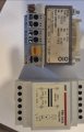
Tested output on transformer and was only outputting 8v. Replaced the transformer for like also. Output is 31v and relay still buzzing.

What I'm confused about is that the relays on the PCB are DC but the old transformer and new transformer both output AC, how did the old transformer work as it was manufactured like this? There is nothing between the transformer and PCB to change the current.

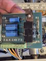
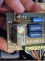
The PCB is rectangular with a relay on either side with 3 capacitors in the middle. Between the relays and the edge of the board there are two diodes on each side.

Images below are the old Transformer next to the new transformer and the PCB

Any help would be appreciated.
 

Attachments

sghioto

Joined Dec 31, 2017
8,633
What I'm confused about is that the relays on the PCB are DC but the old transformer and new transformer both output AC, how did the old transformer work as it was manufactured like this? There is nothing between the transformer and PCB to change the current.
The rectification is on the Relay board.
 

bertus

Joined Apr 5, 2008
22,885
Hello,

Where did you measure the 8 and 31 Volts?
Are that the AC voltages from the transformers?
What DC voltage do you measure on the capacitors?

Bertus
 

MisterBill2

Joined Jan 23, 2018
27,178
I suggest checking the diode!! With the power OFF, use an ohm meter to check the diode in both directions.One direction should approach an open circuit measurement, the opposite should be much lower. The transformer will need to have one of the secondary leads disconnected for the checking. Also, check the relay voltage. Do both a DC voltage check and then set the meter to AC and do another check.
AND, can you show us the other side of the board, including the transformer connections.

The TS should have asked us about doing some checking, before wasting money and effort changing out good parts. Consider that the fuse did not fail for no reason. Most likely is either a shorted diode or a failed capacitor.
 
Last edited:

panic mode

Joined Oct 10, 2011
4,864
both transformers (old and new) have 24VAC secondaries.
rectified DC will be reaching peak voltage with no or only light load. (24 * 1.4 = 33V, or slightly less due to diode)
there seem to be only single diode so rectification would be half wave only. resistor is 1k. values of capacitors or relay are not known, also there is no picture of the bottom side of the PCB.
i would say check diode and replace if necessary. if diode was bad, capacitors are bad too. and judging by the images, this is rather old so it would be a good idea to replace capacitors no matter what.
 

MisterBill2

Joined Jan 23, 2018
27,178
The fact stands that a bit of circuit understanding is mandatory for failure analysis. That includes the fact that in most cases a fuse failing is due to excess current thru the fuse. At that point the TS should have made some voltage measurements, and probably some resistance checks.
 

Thread Starter

BabuBinks

Joined Jun 9, 2025
3
Ive replaced all the capacitors for new. They are all receiving 30v AC. Relay still buzzing, What is my next step?
 

bertus

Joined Apr 5, 2008
22,885
Hello,

Can you post pictures of the top and bottom of the full board?
The capacitors should not have AC on them.

Bertus
 

MisterBill2

Joined Jan 23, 2018
27,178
If the capacitors are receiving 30 volts AC that is a serious problem, indicating failed (shorted) diodes. I described how to test them in post #6.
There should only be DC voltage on the capacitors. What is the voltage on the relay??? Is it AC or DC???
 

MisterBill2

Joined Jan 23, 2018
27,178
These several problems demonstrate exactly why understanding a system or circuit is the first step in repairing it. The very first section of post #1 verifies this. A DC relay suddenly buzzing in a DC circuit is never a relay failure.
Why is it that the TS has not checked the diodes????
 
We are still making assumptions due to lack of info.
There are two relays. No idea which is buzzing or was replaced.
K6 Finder 40.52.7.024.000 DPDT 8A 24VDC with V6, R6 on the coil and maybe C6+C7 who appear in parallel.
The black relay sorta looks like a "smart relay" time-delay but I can't see the p/n. V5, R5, C5 on it.
 

MisterBill2

Joined Jan 23, 2018
27,178
Both of the relays are probably simple DC relays, based on the diode next to each of them. Black relays on appliance PCBs are often single pole, switching mains voltages, with higher temperature rated plastic cases. And in all cases, a relay buzzing indicates the lack of constant coil current. And if the TS is not able to understand about testing the diodes, there is a problem.
IF we could see a complete view of the PCB it is possible that we could be able to tell the TS where the diodes to test wee located. AND some sharp-eyed member might spot the actual problem.
 

MisterBill2

Joined Jan 23, 2018
27,178
ALWAYS, it seems to be the unknowing who replace the wrong part!! Not having any clue as to what the failure may be. And never thinking to check the voltage at the relay. Probably the TS does not even own a multimeter, or know how to use one, or what the readings actually mean.
 
Top