reed switch alarm with a delay turn on help PLEASE

Thread Starter

abdul kayani

Joined Nov 9, 2017
4
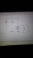
i am currently doing an electronics project which has a reed switch which activates a door alarm for 4 minutes. However, i would like the owner using the alarm 30 seconds to leave the room. i have used a 555 timer monostable to do this and have used a 555 timer monostable to create a 4 minute alarm when the reed switch is broken.

Can anybody help me link the two systems together using a not gate etc.

when the first switch is pressed in my first 555 timer to enable the 30 second turn on delay,onlt then do i want the second 555 timer, which has the reed switch to work. when the reed switch is broken a buzzer or led will sound or light up.

i am using 9v supply
 

dl324

Joined Mar 30, 2015
16,922
Welcome to AAC!

Post a schematic of your two timer circuits.

Off hand, I'd use the 30 second timer to hold the second timer in reset. After it times out, the alarm would be enabled.

BTW, is this project a school project?
 

Thread Starter

abdul kayani

Joined Nov 9, 2017
4
Welcome to AAC!

Post a schematic of your two timer circuits.

Off hand, I'd use the 30 second timer to hold the second timer in reset. After it times out, the alarm would be enabled.

BTW, is this project a school project?
these are the two seperate circuits, i am not the best at electronics but simply need a bit of help. And yes it is a project at school. i have tried using a not gate on thr output of the first 555 timer (3) but i dont know where to go from there. Thank you any help is vital.
 

Attachments

dl324

Joined Mar 30, 2015
16,922
yes it is a project at school
We have guidelines regarding how to deal with work for which you will receive a grade.

What is the objective of this project? Are you supposed to learn how to make the timers work? Or is it about learning how to use them for some application?

Edited screen shots:
clip5a.jpg
clip5b.jpg
 

Thread Starter

abdul kayani

Joined Nov 9, 2017
4
we have to build something that we can use in real life. I chose a burglar alarm. I understand the guidelines but i just do not know how to connect he two circuits together. However, i do understand if you can not help me. Thank You all help is appreciated.
 

dl324

Joined Mar 30, 2015
16,922
I understand the guidelines but i just do not know how to connect he two circuits together. However, i do understand if you can not help me.
What was your idea for using logic gates to connect the two timers?

How will the time period of the alarm timer be affected if the reed switch is opened, but never closes?

Have you calculated the time periods for the one shots? You're using the same component values for both timers, but one needs to be 30 seconds and the other needs to be 4 minutes.

It would be helpful if you posted a PDF of the datasheet you're using so discussion of relevant details can be pointed out to you.
 

Thread Starter

abdul kayani

Joined Nov 9, 2017
4
Since i want the system to not turn on for 30 seconds , essentially a turn on delay, i was thinking of using a NOT gate which would invert the input. In the diagrams above i was testing to see if the delay timer worked with an led. Instead of a resistor and Led i think a not gate should be placed on pin 3 and connected to the second 555 timer.

On the second timer, the pin 5 is supposed to be 10nF instead of uF.

I have worked out the time delay calculations, i was using those so i could check if the circuit worked quicker, instead of watching it for 4 minutes.
The 30 second delay timer has a 27k resistor and a 1000uF capacitor.
The 4 minute timer has a 220k Resistor and a 1000uF capacitor.

The 4 minutes is the minimum time the alarm will be on for, and after that period it will turn off if reset or closed manually.

Thank you.
 

Attachments

dl324

Joined Mar 30, 2015
16,922
Si think a not gate should be placed on pin 3 and connected to the second 555 timer.
Connected where on the second timer?
I have worked out the time delay calculations, i was using those so i could check if the circuit worked quicker, instead of watching it for 4 minutes.
Understandable.
The 30 second delay timer has a 27k resistor and a 1000uF capacitor.
The 4 minute timer has a 220k Resistor and a 1000uF capacitor.
Most of your timing error will come from the capacitors because they typically have a wide tolerance, as much as -20%, +80%, and the leakage current in large capacitors will also impact timing.

Additionally, resistors cost the same regardless of value (in general), but larger capacitors generally cost more than smaller capacitors.
The 4 minutes is the minimum time the alarm will be on for, and after that period it will turn off if reset or closed manually.
What does the datasheet say the timer will do if the reed switch is never closed again?

If you post a PDF of the datasheet you're using, I can point out the relevant information.
 
Top