Reed switch alarm mod

Thread Starter

Izeko

Joined Aug 13, 2019
5
Hi.

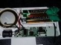
I have bought a cheap alarm that works on a door using a reed switch. How would I replace the way it works so it uses a pressure mat.

The reed switch is closed when the magnet is against it.

Can anyone point me in the right direction.

Thanks
 

Attachments

Bernard

Joined Aug 7, 2008
5,784
Maybe not practical but just to illustrate the action. Assume that mat is high Z and goes low Z with pressure.
Parallel pad with coil of reed relay biased to close SW. With pressure , pad robs current from coil opening reed SW.
Found the word- Velostat, pressure-sensitive conductive sheet.
 

Thread Starter

Izeko

Joined Aug 13, 2019
5
Maybe not practical but just to illustrate the action. Assume that mat is high Z and goes low Z with pressure.
Parallel pad with coil of reed relay biased to close SW. With pressure , pad robs current from coil opening reed SW.
Found the word- Velostat, pressure-sensitive conductive sheet.
I see what you mean here. Only issue would be running it off the battery. As it would drain quite quickly. Is there another way?
 

iimagine

Joined Dec 20, 2010
511
i'd think a 2n7000 would be ok for this, any logic level mosfet would do since u are using 3V supply a 3V logic level mosfet would be best but they are mostly in SMD form
 

Bernard

Joined Aug 7, 2008
5,784
Specs on the mat would be helpful. My guess is output is a variable resistor , about 100k no pressure, a few hundred ohms with a foot. Local battery because door may be some distance from alarm. When reed SW is open there will be V across terminals so installation of new SW may be polarity sensitive.
 

Bernard

Joined Aug 7, 2008
5,784
It is a floating system so either P or N should work? For N ch I use FDD6530A, easy to use SM, 20V, 21 A, LL, G +- 8V , starts conducting @ 1 v G.
On drawing, do we need a connection from battery - to emitter?
 

iimagine

Joined Dec 20, 2010
511
It is a floating system so either P or N should work? For N ch I use FDD6530A, easy to use SM, 20V, 21 A, LL, G +- 8V , starts conducting @ 1 v G.
On drawing, do we need a connection from battery - to emitter?
It just occurred to me that we dont even know which configuration this reed switch is to the MCU, the TS needs to measure and see if it is sourcing or sinking.
 

Bernard

Joined Aug 7, 2008
5,784
Scan.jpg A quick bread board shows that @iimagine circuit works. A simplified closed loop alarm is used; if loop is closed, red LED lights. When the reed SW is removed, polarity of the contacts is measured & then replaced with PS Mat circuit. With 3V supply when PM drops to 8K ohms alarm trips, with 4.5 V @ 4k ohms.
If PM Mat selected does not fit my assumptions then all bets are off.
 

AnalogKid

Joined Aug 1, 2013
10,986
Bernard - for the battery polarity shown, the LED is backwards.

Note that the breadboard worked only because you added a connection between the source and the -batt. The schematic in post #6 is missing the equivalent connection.

ak
 

iimagine

Joined Dec 20, 2010
511
Note that the breadboard worked only because you added a connection between the source and the -batt. The schematic in post #6 is missing the equivalent connection.
Look again, where is the reed switch negative ended up at? isnt it obvious that the intention of the N-mos is pull and short circuit, acting as a closed loop? and if you read post #12, I was unsure if the reed switch is to source or sink and questioned that the TS needs to check. If the reed switch is to source to the MCU then that circuit wont work.
 

Bernard

Joined Aug 7, 2008
5,784
Scan.jpg If the polarity of the loop circuit is the reverse of post # 13, then just flip the PS mat circuit over.
 
Last edited:

marcf

Joined Dec 29, 2014
288
It would be interesting, if you have a multimeter, to measure the voltage across the reed switch with the magnet away from the alarm.

You could also measure the current at the same time.

Having these two measurements, it should be possible to come up with a reasonable circuit. I am guessing that the amount of current in the loop to keep the device out of an alarm condition is pretty low. You could place a variable resistor across the reed switch with the magnet removed and see when the device goes into and out of alarm.

Also, you could measure the voltage at the reed switch in relation to 0v0 (- battery terminals) with the reed switch open (in alarm) and with the reed switch closed ('normal').

I suspect that you could then figure out how to use the pressure mat's open (normal) and closed (alarm) feature.
 

MisterBill2

Joined Jan 23, 2018
18,167
First the TS needs to measure the resistance of the pressure mat with nothing on it, then measure the resistance with one light footstep on it. After that there can be some sensible suggestions. Some mat switches have a very low on resistance and one of those could be used to switch the battery power for the "cheap alarm" shown in post #1. That would be the very simplest way to go.The link describing it, posted by the TS in #4, claims that it is an actual switch. So using it as an actual switch with the alarm assembly shown will be the very simplest way.
But first comes getting the resistance measurements. Until then it is all just guessing, and presuming that the published specification is right..
 
Top