Recommended supply for 12V motor?

Thread Starter

cranberrysky

Joined Feb 15, 2022
54
What do you have available? It must be rated 25VDC or more. Start with 470uF if you have one. Try it first across your power supply without the motor connected. If the supply shuts down on power up, try a smaller value. If it works, you could try a larger one.
Oh, the highest I have is 10uF at 16V. Or 1uF at 160V.

I'm still not entirely clear on why I'd need the capacitor to provide extra current to the motor when it's starting. Why wouldn't the PWM soft start work without the cap?
 

MaxHeadRoom

Joined Jul 18, 2013
30,772
Ah ok. So with soft start, I'd just set the Arduino to analogWrite with a duty cycle of 1, and slowly increase the duty cycle? If a motor draws the most current starting from a stop, won't it still pull a lot of current for the duration of the tiny pulse?
Why do you need an Arduino?
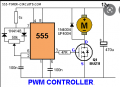
One PWM circuit below,
With PWM, the current is not take the same form the same as the voltage pulse, it takes on a mean current level dependent on the duration of the voltage pulse.

1661804121186.png
 
Last edited:

Jon Chandler

Joined Jun 12, 2008
1,631
Allow me to ask the obvious question – why not get a more capable (higher rated amperage) power supply instead of screwing around with ideas which may or may not work?

A 12 volt, 4+ amp power supply (wall wart) can often be purchased at a thrift store or computer recycler for a couple bucks. The amperage rating can be anything larger than the motor/circuit needs. In the case of a motor, the starting current may be several times the running current.

You might be lucky enough to find an X-Box power supply at the thrift store. These supplies produce 12 – 16 amps at 12 volts. Additionally, these supplies provide 5 volts at 1 amp. But there's another even better feature. The 12 volt supply is turned on by connecting a line to +5 volts. Ground it or leave it open, and the 12 volt supply is off. Hmmm. Sounds a bit like PWM, no? I haven't tested this idea as a motor speed control, but it should work.
 

Thread Starter

cranberrysky

Joined Feb 15, 2022
54
Allow me to ask the obvious question – why not get a more capable (higher rated amperage) power supply instead of screwing around with ideas which may or may not work?

A 12 volt, 4+ amp power supply (wall wart) can often be purchased at a thrift store or computer recycler for a couple bucks. The amperage rating can be anything larger than the motor/circuit needs. In the case of a motor, the starting current may be several times the running current.

You might be lucky enough to find an X-Box power supply at the thrift store. These supplies produce 12 – 16 amps at 12 volts. Additionally, these supplies provide 5 volts at 1 amp. But there's another even better feature. The 12 volt supply is turned on by connecting a line to +5 volts. Ground it or leave it open, and the 12 volt supply is off. Hmmm. Sounds a bit like PWM, no? I haven't tested this idea as a motor speed control, but it should work.
Well, I already have an ATTiny that I was planning to do speed control with anyway, so I'll see if I can make it work without buying anything else. But if not, checking the thrift store is a good idea. And that's interesting about the Xbox supply. I'll definitely keep an eye out for one.
 

Thread Starter

cranberrysky

Joined Feb 15, 2022
54
I actually measured the voltage across the motor and it was only about 9V. I tried with a MOSFET instead of the L293D and was getting north of 11V. I just checked the datasheet of the motor driver, and its max current is 600 mA, so I'm guessing that's why it wasn't getting full voltage. Edit: Oh, I see the L293D has up to a 1.8V drop, so that's probably why it was low.

Can anyone tell me if there are issues with an extremely simple MOSFET circuit: 12V to motor to drain, PWM on the gate through a 1k resistor, and the source, 12V ground and Arduino ground connected?

Now that I think of it, a flyback diode would be a good addition at the least.
 
Last edited:

Thread Starter

cranberrysky

Joined Feb 15, 2022
54
MotorSoftStart.png
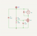
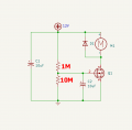
I realized it won't be super important to change the motor speed in the generator, so I wanted to see if I could make a simpler circuit to soft start the motor. I basically copied a circuit I found online, but added a voltage divider so that I could use the 12V source on the gate of the logic level mosfet that has a max 10V. And it works great.

I realize now that there's not much reason for resistors that large since the time constant will be a large 3.3 seconds, but it works fine for me.
 

LowQCab

Joined Nov 6, 2012
5,101
The Maximum-Voltage for the Gate is probably between 15 and 20-Volts.
~10-Volts on the Gate will result in around ~98% of the available RDS-On Resistance from the FET.
( unless this is a "Logic-Level" FET, I don't know what specific part-number this FET is )
( there's no reason to use a "Logic-Level" FET )

Changing the Resistors as shown will provide a Ramp just like You want,
but it will continue to slowly increase the Gate-Voltage until the FET is completely "turned-On",
this will eliminate ~90% or more of the Heat that the
FET would have generated while being held "half-way" On by the first proposed Circuit.
.
.
.
 

Thread Starter

cranberrysky

Joined Feb 15, 2022
54
The Maximum-Voltage for the Gate is probably between 15 and 20-Volts.
~10-Volts on the Gate will result in around ~98% of the available RDS-On Resistance from the FET.
( unless this is a "Logic-Level" FET, I don't know what specific part-number this FET is )

Changing the Resistors as shown will provide a Ramp just like You want,
but it will continue to slowly increase the Gate-Voltage until the FET is completely "turned-On",
this will eliminate ~90% or more of the Heat that the
FET would have generated while being held "half-way" On by the first proposed Circuit.
.
.
.
It is a logic level RFP30N06LE.

Also, maybe you could help me understand how Vds works. When I have the MOSFET fully on (Vgs > 5V), the motor has 11.5V and the other .5V is dropped across the FET. I believe the current is about .5A, so with an Rdson of .047R, shouldn't the voltage be much smaller, like 23mV?

Edit: FYI, it's actually an offbrand version from Amazon called "Weimeet RFP30N06LE".
 
Last edited:

LowQCab

Joined Nov 6, 2012
5,101
There is no "I believe" Current Level.
You could be measuring Motor-Noise, an Oscilloscope will tell the whole story.
This is a "Self-Protecting-FET" which could do strange things when presented with Noise.

Your FET "should" work just fine, is it mounted to a Heat-Sink ?
There is a possibility that it was damaged previously, and is operating in a "crippled-state".
.
.
.
 

Thread Starter

cranberrysky

Joined Feb 15, 2022
54
There is no "I believe" Current Level.
You could be measuring Motor-Noise, an Oscilloscope will tell the whole story.
This is a "Self-Protecting-FET" which could do strange things when presented with Noise.

Your FET "should" work just fine, is it mounted to a Heat-Sink ?
There is a possibility that it was damaged previously, and is operating in a "crippled-state".
.
.
.
Just checked with a multimeter and it is just about .5A going through the FET. Although, this time the voltage drop was only .135V. Or maybe last time I made a mistake measuring. Not too bad, but not as low as I'd expect. Maybe it is damaged. I'll try another one at some point just to see, but this one should be fine for this purpose either way.

Edit: And no, there's no heat sink. I didn't think it'd be necessary with such a small Vds and current.

Another question, is it normal for a switching power supply voltage to drop from 12.1V unloaded to 11.5V loaded at .5A? Or is it because I have a cheap power supply? Edit: Actually, that's just about 1 ohm of internal resistance, not that high, I think.
 
Last edited:

LowQCab

Joined Nov 6, 2012
5,101
Voltage-Drop on "A- SMPS" .............
How close are You running to the maximum-rated-Output of the Power-Supply ?
Some Power-Supplies have rather "loose" Voltage-Regulation,
others may be very tight, until they abruptly go into Current-Limiting or shut-down,
it is what it is, and "sometimes" You get what You paid for.

Your Power-Supply should be rated, at least, ~150% of your Motor's "Locked-Rotor" Current.
--------------------------------------------------------------------------------------------------------------

Heat Dissipation .............
You are currently using the FET as a Resistor to "Ramp-Up" the Motor-Speed smoothly.
During this ramp-up-time, Heat can build-up extremely fast.
This can lead to partially damaging the FET, or even smoking it completely.

If You exceed about 1-Watt of Dissipation, even for just a few seconds,
You may damage or smoke your FET.
Always use some form of Heat-Sink, a bare TO-220-Package is never "OK".
Sometimes things happen really fast.
.
.
.
 

Thread Starter

cranberrysky

Joined Feb 15, 2022
54
Voltage-Drop on "A- SMPS" .............
How close are You running to the maximum-rated-Output of the Power-Supply ?
Some Power-Supplies have rather "loose" Voltage-Regulation,
others may be very tight, until they abruptly go into Current-Limiting or shut-down,
it is what it is, and "sometimes" You get what You paid for.

Your Power-Supply should be rated, at least, ~150% of your Motor's "Locked-Rotor" Current.
The supply is rated for 3A. I'm pretty sure the stalled current is higher than that because it resets the power supply if I add too much load.

Heat Dissipation .............
You are currently using the FET as a Resistor to "Ramp-Up" the Motor-Speed smoothly.
During this ramp-up-time, Heat can build-up extremely fast.
This can lead to partially damaging the FET, or even smoking it completely.

If You exceed about 1-Watt of Dissipation, even for just a few seconds,
You may damage or smoke your FET.
Always use some form of Heat-Sink, a bare TO-220-Package is never "OK".
Sometimes things happen really fast.
Ok good to know, I'll be sure to add one.
 
Top