recomended Voltage Follower

Thread Starter

lordofentropy

Joined Apr 10, 2010
58
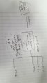
Any recommendations for a voltage follower, I have a 10V, 2.5mA signal that I need to boost it's current say around 40mA. I believe this signal is being used on multiple RTD probes, and instead of reading one at a time they want to read like 16 at the same time, so obviously that's to much load for the initial 2.5mA signal.
Above assumes I am connecting all RTD's to the same output of the voltage follower, however, (another question) is there any thoughts on isolating each RTD on it's own voltage follower? That would basically mean I would need to take the 10V/2.5mA input signal and reproduce it 16 times.

Thanks
 

Papabravo

Joined Feb 24, 2006
21,157
What exactly is the result of "reading" 16 probes at one time. What does that result even mean?
Does it mean you have 16 probes in parallel!!??
 

Thread Starter

lordofentropy

Joined Apr 10, 2010
58
This isn't my idea, to read all of them at once. But electrically speaking, if they were all connected to the same bus/voltage follower then yes you can considered them all in parallel.
 

crutschow

Joined Mar 14, 2008
34,280
How are "they" reading "like" 16 probes at a time if they are in parallel?
Do they want the average value of the 16?
Are you generating a voltage signal or a current signal?
 

Thread Starter

lordofentropy

Joined Apr 10, 2010
58
I don't know how they are setting them up to read them, assuming through some type of lab view interface (does this really matter?), but that's an assumption b/c it's as I said it is in fact a 'they'. Again, the signal I was told I have to work with is a 10V/2.5mA signal that is generated from some black box that I know nothing about. This signal is used to connect (rather power) to one sensor at a time. However, the person wants to use this signal and power all 16 sensors at one time, why? I don't know. How is he handling it, i don't know, to what end, I don't know. They will obviously all be connected in parallel in some way due to the fact that this signals current needs to be either amped up and all sensors connected to a bus or the initial signal needs to feed parallel voltage followers connected to the signal and feed into the various sensors, Either way its parallel.
And again, I am not generating the signal, Its generated from something else being used on RTD probes which actually generate a change in resistance by a passing current which is measured as a voltage, which specific RTD (possibly another question someone will ask, no)

I just need voltage follower suggestions for the 10V/2.5mA signal, therefore no schematic and there is no schematic to begin with b/c I have no idea how he is wiring these or even if they are 2 wire, 3, or 4 wire RTD's.
 

Alec_t

Joined Sep 17, 2013
14,280
What power supply do you have available for a circuit to do the buffering?
How rapidly is this signal likely to change, and by how much?
 

Thread Starter

lordofentropy

Joined Apr 10, 2010
58
obtaining a power supply, is not a problem. Right now, +12VDC and +15VDC I know for a fact are readily available, also possibly +-6/+-24 might also be available, not sure on it.
 

AnalogKid

Joined Aug 1, 2013
10,986
I don't know why? I don't know. How is he handling it, i don't know, to what end, I don't know.
I did a few years building instrumentation for university research groups, so I feel your pain.
What power is available to power the voltage follower circuit? IOW, where does the 40 mA come from? +15 Vdc would be nice.
Also, is the 10 V a constant, or does it vary under process control?
And just to make sure, what is your skill set for building a small circuit on perf board or some other technique?

If the 10 V is a constant voltage, then one opamp and one NPN transistor should do it.

If the 10 V / 2.5 mA source actually is a 2.5 mA constant current source with a 10 V compliance, that is a very different thing. It kinda makes sense for powering one sensor with no other current limiting device or series resistor to form a divider, but makes an expander circuit more complex.

ak
 

Thread Starter

lordofentropy

Joined Apr 10, 2010
58
I did a few years building instrumentation for university research groups, so I feel your pain.
What power is available to power the voltage follower circuit? IOW, where does the 40 mA come from? +15 Vdc would be nice.
Also, is the 10 V a constant, or does it vary under process control?
And just to make sure, what is your skill set for building a small circuit on perf board or some other technique?

If the 10 V is a constant voltage, then one opamp and one NPN transistor should do it.

If the 10 V / 2.5 mA source actually is a 2.5 mA constant current source with a 10 V compliance, that is a very different thing. It kinda makes sense for powering one sensor with no other current limiting device or series resistor to form a divider, but makes an expander circuit more complex.

ak
THANK YOU!!! Finally someone who understands! lol.
Power is no problem, as I said I know for a fact +12VDC and +15VDC is there, and I can also throw in a power supply. 40mA came from assuming this magic black box that is being used (it's 10V/2.5mA signal is an analogue output from the box) is used to drive 1 sensor at a time, so the 40mA came from just multiplying the 2.5mA * 16 sensors, figured that would be a good starting point would have to put in current resistors so each would not draw to much if all one bus but no biggie.

Skill set for making boards/soldering/smd's/etc. is excellent.

It's a 10V constant voltage from the box.
 

crutschow

Joined Mar 14, 2008
34,280
Yes, our questions really matter. :)
The reason we ask so many questions is because an OP often asks how to implement his perceived solution to problem when the actual problem is different from his perception.
So we like to pin down the actual problem, not the perceived solution, before we offer our own solution.

So what's the required accuracy between the buffer input and the buffer output voltage?
How much difference can there be?
 
Last edited:

AnalogKid

Joined Aug 1, 2013
10,986
National Semi (now TI), Burr Brown (now TI), Apex, and others make single-chip opamps with high output current capability, so a simple voltage follower circuit with one of those parts will be the least effort. If you already have some opamps you want to use, then a small power transistor like a TIP29 or TIP31 on the output will boost the current.

http://terpconnect.umd.edu/~toh/ElectroSim/Booster.html

ak
 

Papabravo

Joined Feb 24, 2006
21,157
Wait a second. An RTD probe is a passive resistive device that is used in a bridge circuit. They come in two wire and four wire configurations. In the 4 wire case there is a constant current source that supplies the resistor in the RTD and a second pair of wires that measures the voltage.

See the following article for a picture.

https://en.wikipedia.org/wiki/Resistance_thermometer

Is this what we are talking about? If so doing the probes in parallel makes absolutely no sense. It looks like what you need is just 16 current sources and 16 DVMs, and you can throw away the original black box
 

MrChips

Joined Oct 2, 2009
30,703
Communication, communication, communication!

Let's scrap the title of this thread and start all over again.

So you have 16 two-wire resistance temperature detectors (RTD) and and you wish to measure the resistance of each RTD with a single circuit

Is that what you are trying to do?
 

Thread Starter

lordofentropy

Joined Apr 10, 2010
58
There is no communication, I wish there was.
I personally do not have the RTD's, he wishes to have this 10V signal spread across all RTDs, a buffer. I assuming he already has a specific way of wiring them up. In fact, lets scrap RTDs. The guy has 16 sensors, all I need to do is get this signal to all of them, I get the problem (RTDs in series [resistance of RTDs will add], etc.) I do not know the specific ones he has.

So basically I have 16 sensors, I need to get 10V/2.5mA to each one with having only a 10V/2.5mA signal.
 

ian field

Joined Oct 27, 2012
6,536
This isn't my idea, to read all of them at once. But electrically speaking, if they were all connected to the same bus/voltage follower then yes you can considered them all in parallel.
Sounds like you need to multiplex them with CMOS analogue switches.

Unbuffered from the 4000 CMOS family might do - but the RDSon could be a problem, and your signal mustn't exceed Vdd.

Other than that - there's whole families of industry standard analogue switch ICs that should provide a part that doesn't degrade signal integrity.
 

Thread Starter

lordofentropy

Joined Apr 10, 2010
58
Yes and the power specifically is coming from this box, that power is a 10V/2.5mA, (25mW), using that power I need to get it to 16 of them. Therefore, I need a voltage follower. Please list your favorite op amps that can do the job.
 

Papabravo

Joined Feb 24, 2006
21,157
There is no communication, I wish there was.
I personally do not have the RTD's, he wishes to have this 10V signal spread across all RTDs, a buffer. I assuming he already has a specific way of wiring them up. In fact, lets scrap RTDs. The guy has 16 sensors, all I need to do is get this signal to all of them, I get the problem (RTDs in series [resistance of RTDs will add], etc.) I do not know the specific ones he has.

So basically I have 16 sensors, I need to get 10V/2.5mA to each one with having only a 10V/2.5mA signal.
So you can have 16 voltage followers, or you can have 16 current sources that output 10V @ 2.5 mA. If you go with the individual sources you can adjust/calibrate them independently. If you go with voltage followers then you are going to have some variability, which may or may not be a good thing. The problem with an adjustable follower is that you can only have a gain greater than or equal to 1.
 
Top