Read analog low-pass filter to Arduino

Thread Starter

Aresvy

Joined Feb 2, 2018
11
Hello,
I would like to have a Little help with a Project i'm making.

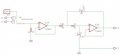
I need to read the signal of a second order low-pass filter to the serial plotter in the Arduino IDE.
The problem is a have concerns about how enter the signal; I just put the output of the circuit into the arduino and program the Arduino to read the signal?

I'll be greatful for any kind of help, thanks.
 

ericgibbs

Joined Jan 29, 2010
18,766
hi,
I guess you know that the amplitude of a signal into an Arduino must not exceed the supply voltage to the MCU, ie: 3.3v or 5v.
and it must swing between 0v and that limit, but not below 0v, ie: a negative voltage.
Are you planning to use an Analog input on the Arduino or a Digital signal.?
If you post a circuit sketch it would help us.
E
 

shteii01

Joined Feb 19, 2010
4,644
Ok.
First. When you say Arduino, I assume you mean Uno board. If you want to come across like a half competent person, never say Arduino because Arduino FOUNDATION has a dozen or more boards on the market.

Second. 7 volts is too much. I don't think you will fry ATmega328 chip, but, like Eric is trying to worn you, the ADC of Uno board is designed to read signals between 0V and Uno supply voltage. Since I assume you have Uno, your ADC range is 0V to 5V. THAT IS IT. What this means is that when you apply 7V, and assuming 7V will not fry ADC section of ATmega328, your Uno will show 5V because that is the maximum it is capable of reading. The old sci fi short story applies here: The Machine DOES NOT Care. Same for the voltages below 0V. If your signal oscillates below 0V, Uno will show 0V because that is the minimum it can read.

Third. I don't know off hand the sampling frequency of Uno ADC (ATmega328), but I assume it is in kHz so the very low frequency of your signal (1.4 Hz) is fine.

Fourth. Transfer function does not matter since ADC does not care, the ADC expects an analog signal from 0V to 5V at a frequency well below its sampling frequency.

Fifth. You will need to condition your signal before you feed it to Uno ADC.
- You gave us amplitude, but you don't tell us if the signal goes below 0V. If it does, you will need to move it up. Some kind of voltage shifter circuit.
- As been said twice now, 7V is too much for Uno (Uno will not record your signal accurately), you will need to reduce/attenuate your signal. Voltage divider commonly used. You can add buffer if it is sensitive stuff.
 

Thread Starter

Aresvy

Joined Feb 2, 2018
11
Ok.
First. When you say Arduino, I assume you mean Uno board. If you want to come across like a half competent person, never say Arduino because Arduino FOUNDATION has a dozen or more boards on the market.

Second. 7 volts is too much. I don't think you will fry ATmega328 chip, but, like Eric is trying to worn you, the ADC of Uno board is designed to read signals between 0V and Uno supply voltage. Since I assume you have Uno, your ADC range is 0V to 5V. THAT IS IT. What this means is that when you apply 7V, and assuming 7V will not fry ADC section of ATmega328, your Uno will show 5V because that is the maximum it is capable of reading. The old sci fi short story applies here: The Machine DOES NOT Care. Same for the voltages below 0V. If your signal oscillates below 0V, Uno will show 0V because that is the minimum it can read.

Third. I don't know off hand the sampling frequency of Uno ADC (ATmega328), but I assume it is in kHz so the very low frequency of your signal (1.4 Hz) is fine.

Fourth. Transfer function does not matter since ADC does not care, the ADC expects an analog signal from 0V to 5V at a frequency well below its sampling frequency.

Fifth. You will need to condition your signal before you feed it to Uno ADC.
- You gave us amplitude, but you don't tell us if the signal goes below 0V. If it does, you will need to move it up. Some kind of voltage shifter circuit.
- As been said twice now, 7V is too much for Uno (Uno will not record your signal accurately), you will need to reduce/attenuate your signal. Voltage divider commonly used. You can add buffer if it is sensitive stuff.
Thanks for the help.

yes, I'm using an Arduino UNO for this Project; i'm supplying the circuit with 5V, the respond of the filter is in second order, if I keep pressing the push-button it stays in 5V, if I leave the button it goes back to 0 V.

Using a voltaje divider sound a good idea to lower the output and don't break the Arduino.
 

shteii01

Joined Feb 19, 2010
4,644
Thanks for the help.

yes, I'm using an Arduino UNO for this Project; i'm supplying the circuit with 5V, the respond of the filter is in second order, if I keep pressing the push-button it stays in 5V, if I leave the button it goes back to 0 V.

Using a voltaje divider sound a good idea to lower the output and don't break the Arduino.
Do you have the ability to look at the signal on the oscilloscope?
 

MrAl

Joined Jun 17, 2014
11,389
Hello,

Just as quick note...

In conditioning the signal you probably also have to use an isolation amplifier with relatively high impedance so you dont 'load' the signal to be measured. Typically an op amp would be used, non inverting for example.
Also, when i look around on the web the ADC input is not very well understood. During the conversion, the input impedance may be lower than normal, and the leakage current can sometimes be a factor also making an input isolation amplifier a very good idea as it takes care of all these problems. The only exception is when your signal has a nice low output impedance already, like 50 ohms, 100 ohms, but not too much higher.
 

ericgibbs

Joined Jan 29, 2010
18,766
hi aresvy,
Your circuit requires a dual supply in order to work correctly, please confirm that the supplies are +/-5v.?
When using a dual supply the Vout [ into the ADC ] swings +/-V about 0V.
The Vout also is 'clipped' at +/-3.5v for a Vin of > 2Vpk.
The Vout signal is not suitable for direct connection to a Arduino UNO analog input.

We require more details of the actual input voltage and source.

E
 

Attachments

shteii01

Joined Feb 19, 2010
4,644
hi aresvy,
Your circuit requires a dual supply in order to work correctly, please confirm that the supplies are +/-5v.?
When using a dual supply the Vout [ into the ADC ] swings +/-V about 0V.
The Vout also is 'clipped' at +/-3.5v for a Vin of > 2Vpk.
The Vout signal is not suitable for direct connection to a Arduino UNO analog input.

We require more details of the actual input voltage and source.

E
TL082 supply goes up to +/-15V, so total range is 30V and usable range of 20V or a little more.
Your original point stands. Whatever OP is feeding the ADC, it will be too much.
 

ericgibbs

Joined Jan 29, 2010
18,766
hi 01,
The TS did say he is using a single 5V supply, which will not get the result he is expecting, its got to be dual supply.
Hopefully he will come back with more info.
E
 

Thread Starter

Aresvy

Joined Feb 2, 2018
11
Op said signal amplitude is 7.104. I assume volts.
I'm using a voltaje supply to use the TL082, i'm suplying the Opamp with 15V+ and 15V-.
The 5 volts is for a unitary scale which activated by a button, giving me an second order response, as shown in the schematic.
schematics.JPG response.JPG
 

Thread Starter

Aresvy

Joined Feb 2, 2018
11
hi Aresvy,
This is what LTSpice shows, do you have a question.?
E
Yes, my question is: How can I graph that response in the serial plotter in Arduino Uno?
I can put the response from my circuit to the Arduino, make a code and graph it?
In the answers adove tells me that needs to lower down the voltage less or equal to 3.3V or 5V to not damage the Arduino.
It is possible to down the voltage with a simple voltage divider or I need something else?

Thanks.
 

ericgibbs

Joined Jan 29, 2010
18,766
hi,
Have you tried using the serial plotter tool in the Arduino IDE, then using a screen grabber to get it as an image.?
E
Use a simple resistive divider to drop the 5V in step.

EDIT:
Look at this option.
 

Attachments

shteii01

Joined Feb 19, 2010
4,644
Yes, my question is: How can I graph that response in the serial plotter in Arduino Uno?
I can put the response from my circuit to the Arduino, make a code and graph it?
In the answers adove tells me that needs to lower down the voltage less or equal to 3.3V or 5V to not damage the Arduino.
It is possible to down the voltage with a simple voltage divider or I need something else?

Thanks.
I used plx-daq: http://forum.arduino.cc/index.php?topic=437398.0
 

Thread Starter

Aresvy

Joined Feb 2, 2018
11
hi,
Have you tried using the serial plotter tool in the Arduino IDE, then using a screen grabber to get it as an image.?
E
Use a simple resistive divider to drop the 5V in step.

EDIT:
Look at this option.
Thanks for the help.
I'm using the voltage divider and tryng to use the serial plotter but only I can see the spikes of the response.
 
Top