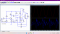
you use ideal transistors
10uF takes time to charge up
10V modulation is perhaps too high and it's not decoupled
100nF might be insufficent for reliable coupling
10uH for HF decoupling may be too low
(also the oscillator part looks unknown/exotic to me)
Two days later the oscillator circuit still does not look right. And checking against references in the ARRL handbook, the oscillator IS NOT RIGHT!
In addition, the modulation signal is way to great, it is altering the operating point of the oscillator.
So the very first thing to try is removing the modulation signal and see what the oscillator does without being vastly over driven by the modulation input.
It seems that not every bit of information presented on line is accurate. The AAC site seems to do better than many in that regard.
Post #4 is correct in stating the concern about the oscillator circuit. If it were correct it would be a version of the classic "Collpits" oscillator, but it looks to me as though the feedback is the wrong polarity. Most oscillator circuits use positive feedback to sustain oscillation, which implies a loop gain of greater than +1. THAT is not what I see.
No, it's definitely a Colpitts. The junction of the capacitors is grounded, but drawn badly so it looks confusing. The ratio of C8 to C9 is all wrong and it lacks a capacitor from Q2 collector to the tank so out has a DC offset. C4 is not needed in the feedback loop. I'm not convinced by having inductors as the collector loads. The biassing is off too. It's supposed to oscillate at 91MHz, bottom of FM band, which sort of makes sense.
made some mods out of the thin air . . . i decoupled your signal source with 330pF , reduced the signal level to ±500mV pk-pk , increased the L1 to 400uH set a limitting resistor in series with C7 , altered the oscillator part (! conceptually ~ quite a lot ~ dual neg. ~AC feedback !) - it became a stable FM for the tested first 200us - but due my biasing scheme i doubt it would work at real world (Mohm range) ~ although it simulates . . . (i don't want to suggest my fusions - basically a blind guesses made by the spice response... - coz they may be off the initial concept of your circuit's src. ??)

 Facebook
 Google
 GitHub
 Linkedin