Ratio Detector question

Thread Starter

Gabrigam66

Joined Oct 9, 2014
2
Hi,

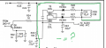
I built the attached ratio detector circuit and it works but
I can't understand the reason for the connection marked in green.

I need an explanation, please.

Thanks in advance.

Gab
 

Attachments

MisterBill2

Joined Jan 23, 2018
27,507
Without that connection there is no return path for the audio signal. That is the main purpose. In addition, it provides a bias for the AFC circuit. Those are the obvious purposes, there may be others, since the rest of the circuit is not shown.
 

MisterBill2

Joined Jan 23, 2018
27,507
The green colored conductor supplies dc voltage to the detector and the 2nd IF.
REally, there are two different conductors. The split is at the V+ sign on top. My reference is to the portion that extends to the positive terminal of C25. The part that extends down to the positive terminal of C23 does indeed power the last IF stage.
 

Thread Starter

Gabrigam66

Joined Oct 9, 2014
2
Without that connection there is no return path for the audio signal. That is the main purpose. In addition, it provides a bias for the AFC circuit. Those are the obvious purposes, there may be others, since the rest of the circuit is not shown.
It looks like it is automatic gain control by varying the operating point of Q6.

Where did you get the circuit?
Hi,

the circuit related to a radio fm am kit available in internet: MODEL AM/FM-108CK SUPERHET RADIO ELENCO

Thanks


Thanks
 

DbLoud120

Joined May 26, 2014
99
Hello,
It has a label, audio output, and AFC.
The audio is coupled with a capacitor then fed to an audio power amp.
DC voltage is fed directly to the AFC stage.
See attached for schematic and assy. instructions.
The explanation for this stage is in instructions.
 

Attachments

Ylli

Joined Nov 13, 2015
1,092
The connection of V+ to the plus end of C25 is not necessary for the operation of the Ratio Detector itself. But the detector is also being used to provide AFC back to the local oscillator, and a bias on that line is required to put the AFC line at the proper operating point. The point the V+ is connected is just a convenient point that it can be added in without affecting the audio output of the RD.
 

MisterBill2

Joined Jan 23, 2018
27,507
What is the voltage at C23 on a dead carrier? Isn't it suppose to be zero?
There is no reason for the DC voltage at the output to be zero when there is no modulation, The DC level is set to conveniently work with the AFC (automatic Frequency Control) circuit. Also, consider that since FM delivers the noise removal function mostly by keeping the amplitude clipped, IF stages for FM are often limiters. While a ratio detector does not demand limiting of it's input, a limiting stage prior to the ratio detector will reduce noise on weaker signals. So look at the block diagram and observe that there is NO AGC function.
 

BR-549

Joined Sep 22, 2013
4,931
I use to work on a lot of commercial FM narrow band transceivers years ago. Lot's of alignment work.

Wide band ratio detectors must be different.

Zero volts, was the AFC reference. It allows a plus and minus correction.

Most of my work was on GE equipment, maybe moldyoldy(Motorola) was different.

Tune in strong a FM station. Lift the voltage bus at C25 and listen.
 

MisterBill2

Joined Jan 23, 2018
27,507
I use to work on a lot of commercial FM narrow band transceivers years ago. Lot's of alignment work.

Wide band ratio detectors must be different.

Zero volts, was the AFC reference. It allows a plus and minus correction.

Most of my work was on GE equipment, maybe moldyoldy(Motorola) was different.

Tune in strong a FM station. Lift the voltage bus at C25 and listen.
Those radios used a different sort of arrangement to vary the tuning. And those ratio detectors did have a common connection to circuit ground, which the posted one does not have. So if the AFC voltage needs to be other than zero when it is on frequency then somehow that bis needs to be provided. A series connection like the one shown is simple and adequate.
 
Last edited:
Top