Random Time 555 Timer

Thread Starter

iONic

Joined Nov 16, 2007
1,662
OK all,

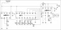
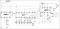
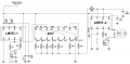
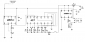
This is a real stumper for me. I'd like to to be able to use a momentary, N.O. push button switch to start a timed on circuit. In other words when I press the N.O. switch a buzzer come on but with an unknown time length.

My first thoughts were to meld a constantly operating 4017(sort of a random dice generator) circuit with a 555 timer, but the RC time constant would be governed by the resistance from the 4017 outputs.

I think, I KNOW the circuit I built below is wrong and would like some help fixing it, that is if a 4017 can do the trick. If not, what can?

Thanks
 

Attachments

Last edited:

mik3

Joined Feb 4, 2008
4,843
Nanovate, this not the only problem, there are faulty connections on the 555s and maybe on the 4017.

Ionic, I want to know why do you need this random turn on of the buzzer? Maybe you can make a simpler circuit.
 

Thread Starter

iONic

Joined Nov 16, 2007
1,662
Nanovate, this not the only problem, there are faulty connections on the 555s and maybe on the 4017.
Yes, C1 is blocking the power, dumb of me. Are there more mistakes? Absolutely.

Ionic, I want to know why do you need this random turn on of the buzzer? Maybe you can make a simpler circuit.
Personally I think the "I want" and the "why" is irrelevant but I don't want to scare anyone away from helping. Rest assured it is not for anything mischievous. I'm not sure if there are mischievous intents implied in my initial post or not. I'm simply trying to answer a question, without a micro controller and programming can the RC time constancy of the 555 be randomly selected sort of like the roll of the dice, for example between 15 sec and 2 minutes. If there is a way to do this without the final 555 then this is OK too, but it does need to be isolated by a relay. The trigger I assume, on the circuit I drew up would have to be initiated at the 4017.

I made a few changes to the circuit above. 555-1 just sets the osc. freq. for the 4017. I believe this 555 is wired fine. The 4017
should just be cycling through its outputs until the N.O. push button is pressed, theu selecting a different resistance to use in the 555-2 circuit. This interconnection is where I am unsure of.
 
Last edited:

mik3

Joined Feb 4, 2008
4,843
I am sorry Ionic, I didn't mean to learn something about you by asking why. I wanted to see if it is necessary to do it in this way.
Anyway,
-the left 555 looks fine
- reverse the diode across the relay coil
- remove the push button and connect R7 directly to pin 7 of the right 555
- move the 5M variable resistor on the left side of pin 7
- use the push button with a resistor on pin 2 to trigger the right 555
- connect the output of the right 555 to the enable input of the 4017 via a 10K resistor.
 

Thread Starter

iONic

Joined Nov 16, 2007
1,662
I am sorry Ionic, I didn't mean to learn something about you by asking why. I wanted to see if it is necessary to do it in this way.
Anyway,
-the left 555 looks fine
- reverse the diode across the relay coil
- remove the push button and connect R7 directly to pin 7 of the right 555
- move the 5M variable resistor on the left side of pin 7
- use the push button with a resistor on pin 2 to trigger the right 555
- connect the output of the right 555 to the enable input of the 4017 via a 10K resistor.
Not a problem mik3,
I've been in a couple of situation myself where I was unsure if I should help someone build a project where it appeared to be either dangerous or the builder seemed to be totally clueless. I am sometimes not too far from the clueless sometimes, but I know this when dealing with questionable voltages and know how to take the right precautions.

Anyway, I made the changes you recommended and felt a couple of "Oh Yeah, I knew that's" rush through me.

Granted, the resistors for the RC time constant(s) are not right, but theoretically it seems doable.

Appreciate the help.

iONic
 

Attachments

SgtWookie

Joined Jul 17, 2007
22,230
It's not going to be very random with just 10 possibilities.

Now if you had an 8-bit R2R ladder that was being driven by a free-running clock and interrupted by a human-influenced pushbutton, then that could approach randomness.
 

Søren

Joined Sep 2, 2006
472
Hi,

A free running triangle oscillator at a fairly low frequency, with a sample/hold circuit to "grab" the voltage at the instant the button is pushed, would appear "random" to the button "pusher".

The same contact could start a ramp going from V_lo to V_hi in 120 seconds (just resetting a cap charging through a resistor should be fine - a transistor could do that, preferably through a small cap).

A comparator could then switch on when the button is initially pressed and off again when the voltage on the cap reaches the voltage held by the s/h circuit.

V_lo and V_hi should be selected to comply with 15 and 120 seconds respectively.

A dual comparator (or opamp in a pinch) would be the only IC needed.
 

mik3

Joined Feb 4, 2008
4,843
You have connected the output of the 555 to pin 12 of the 4017. This is wrong, connect it to pin 13 of the 4017. Also, disconnect the wire connecting pins 13 and 15 of the 4017 and connect pin 15 to ground.
 

Thread Starter

iONic

Joined Nov 16, 2007
1,662
It's not going to be very random with just 10 possibilities.

Now if you had an 8-bit R2R ladder that was being driven by a free-running clock and interrupted by a human-influenced pushbutton, then that could approach randomness.
Your right again! It's predictable 1 of 6 times based on the 4017 configuration.
 

Thread Starter

iONic

Joined Nov 16, 2007
1,662
Woah! I think the first 555 section is wrong as well as the 4017. I did not get any pulse from the first 555 and when I changed it somewhat I did. Then I didn't get any changing of the LED on the 4017, Pin 3 was always lit. I changed this and will be trying this out soon. New circuit is below:
 

Attachments

mik3

Joined Feb 4, 2008
4,843
Change Rxa to 1K and Rxb to 20K to achieve a pulse waveform with a duty cycle close to 50%.
Also, the circuit you don't need a transistor to drive a led from the 555. Just a 1K resistor and the led in series can be driven directly form the 555 because it can supply up to 200mA and the led needs only 20mA.
Also, if you want, connect the enable pin of the 4017 to the output of the 555 to stop the counting on a particular resistor when the right 555 starts to count the time.
 

Thread Starter

iONic

Joined Nov 16, 2007
1,662
Change Rxa to 1K and Rxb to 20K to achieve a pulse waveform with a duty cycle close to 50%.
Will do.

Also, the circuit you don't need a transistor to drive a led from the 555. Just a 1K resistor and the led in series can be driven directly form the 555 because it can supply up to 200mA and the led needs only 20mA.
You are right there.

Also, if you want, connect the enable pin of the 4017 to the output of the 555 to stop the counting on a particular resistor when the right 555 starts to count the time.
Don't think I want this though.

Q: if I reduce the input voltage to about 4V then I ought to be able to connect white LEd's(3.6Vf) directly to ground and they should cycle?
I say this because the circuit is still not working(1st 555 with the 4017).
 

mik3

Joined Feb 4, 2008
4,843
The 555 needs more than 4.5V to work. Even if you reduce the voltage down to 4.5 you will need a small value resistor for current limit because the voltage across the led is not constant but it varies a bit. Even a small variation can cause a large increase in the current through the led. Always use a resistor in series with the led. Disconnect th5 555 from the 4017 and test it alone to see if it is working. Check its output with a multimeter.
 

Thread Starter

iONic

Joined Nov 16, 2007
1,662
The 555 needs more than 4.5V to work. Even if you reduce the voltage down to 4.5 you will need a small value resistor for current limit because the voltage across the led is not constant but it varies a bit. Even a small variation can cause a large increase in the current through the led. Always use a resistor in series with the led. Disconnect th5 555 from the 4017 and test it alone to see if it is working. Check its output with a multimeter.
The 555 seemed to work fine below 5V... even to 3V. I'm gonna replace the 4017 and re wire it, and exclude the 555. It has been very cold here and very dry and although I do not have any carpets, static electricity could have gotten the better of this device...either that of mis-wiring.
 

Thread Starter

iONic

Joined Nov 16, 2007
1,662
OK,
We got it. The 4017 was bad. once I got the 4017 running I added the 555 clock, all was well, but when I swapped the the old 4017 in, it died...didn't work.
So stage 1 and two are working, stage 3 is built. Stage 3 is also working. But when I connect stage 1 and 2 to stage 3 the relay turns on and stays on.

All ten LEDs lit and rotated fine on their own so I replaced all but 1 with resistors to be used in the final 555 timer and connected to timer 2.

Any ideas?
 

Attachments

Thread Starter

iONic

Joined Nov 16, 2007
1,662
I don't understand the problem, explain it better please.
When I press the momentary switch on 555-2 the relay comes on with an indicator LED, but does not turn off. It doesn't seem to be adding the resistances from the 4017 to the 330K of the 555-2 circuit to make a different on time.

I will connect the 330K resistor from the 555-2 circuit directly to the output pins of the 4017 to see if I am getting the same 10s on time I get when connected to +V source.
 
Top