Rain Simulator / Ocean Sounds Circuit Design

Thread Starter

em_cardc

Joined Apr 5, 2016
43
Hello AAC!

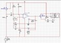
I need the most background and help with creating a simple way of getting a Rain Drop Simulating Circuit with op-amps, BJTS, Caps and Resistors where I can create the closest to variations of rain drops or ocean sounds (I think the ocean sounds would be simpler?). I've been looking around to see sample rain drop simulating circuits but haven't had much luck with simple designs for a student design project. Is there anybody out there that could help me around with this? Best way would be a head start, what kind of filters would I need / how many/ etc? Options... etc? I am using multisim/physical components to create and simulate.
 

MrChips

Joined Oct 2, 2009
30,706
A reversed biased PN junction is a good source of white noise. Take an NPN transistor and amplify the signal from the reversed biased base-emitter junction.

noise generator.jpg

Here is the circuit from a construction project "The Drummer Boy" from Popular Electronics July 1971.

Q31 is the noise source. Q32 amplifies it. T1 and C50 changes the "color".
 

#12

Joined Nov 30, 2010
18,224
These are good noise generators but I wouldn't expect them to be satisfactory without some tone controls. A cheap speaker will roll off some high frequencies, but I'll bet you find a tone control or two will make them a lot more versatile. Simple RC filters should work pretty well.
 

KJ6EAD

Joined Apr 30, 2011
1,581
I used the old SN76477N complex sound generator chip with it's white noise source and filters to create effective wind, surf and rain sound effects for a project once. If I had it to do now, I'd look for canned samples first and synthesizer algorithms second.

Try this search term in google:
surf+wind+rain+sound+effect+synthesis
 

AnalogKid

Joined Aug 1, 2013
10,986
Raindrop simulation is very difficult without just sampling and replaying an audio signal. Ocean waves are relatively easy if you like *lots* of opamps.

Start with a white or pink noise generator circuit. Follow that with both voltage-controlled amplifiers and voltage-controlled bandpass filters. These combine to shape the noise into the swell / crash / ebb pattern of the volume of a wave, and the change in frequency from the low boom of the crash to the hiss of the ebb.

ak
 
Last edited:

Thread Starter

em_cardc

Joined Apr 5, 2016
43
I want to know if this looks right. This is my approach to Ocean Wave Sound Generation. Thing is I am simulating it on Multisim and I am not getting an output sound through the simulated speaker. Can anyone tell me if there's anything wrong with my circuit diagram?
 

AnalogKid

Joined Aug 1, 2013
10,986
The opamps need reference designators and part numbers.

The non-inverting input of the first opamp needs to be connected to 6 V to give the circuit a DC reference. Otherwise, the output will saturate either high or low due to offset errors.

Same for the 2nd opamp unless it is an LM386 (which is not an opamp).

What is the purpose of the switch and C3?

ak
 

Thread Starter

em_cardc

Joined Apr 5, 2016
43
The opamps need reference designators and part numbers.

The non-inverting input of the first opamp needs to be connected to 6 V to give the circuit a DC reference. Otherwise, the output will saturate either high or low due to offset errors.

Same for the 2nd opamp unless it is an LM386 (which is not an opamp).

What is the purpose of the switch and C3?

ak

The switch was only intended in case I would implement other sounds. (So basically this switch won't be used and the capacitor remains connected as is.

I don't know if I understood what you said about adding a DC reference to my second op amp since the inverting is connected to a resistor wheras the non inverting is conected to the potentiometer. Could you please specify a little more about this issue? Also, I noted on multisim there's no LM386. Is there an alternative for this? Thank you for your feedback.
 

AnalogKid

Joined Aug 1, 2013
10,986
A 741 cannot drive an 8 ohm speaker. Read the datasheet to see what its limitations are. To drive a speaker with an IC, you need one designed specifically for that.

Also, a 741 does not have any input biasing circuits inside. It needs a DC reference potential on its non-inverting input, or the output will saturate.

ak
 

wayneh

Joined Sep 9, 2010
17,496
Is there a DC power source in there? It looks like you're powering the opamp with your signal, which is also applied to the output transistor. That won't work.
 

gwildes1

Joined Dec 29, 2017
6
I kept experimenting until I came up with something that seems to work really well, with a pot for tuning in a range of noise from white, to pinkish, to crackle, also an external input for amplitude modulation. It needs at least 12V, won't work with 9V. I tried a few different transistors, 2N4401 and 2N2222 worked better (noisier) than 2N3904.

upload_2017-12-29_14-30-20.png
 

AnalogKid

Joined Aug 1, 2013
10,986
1. This thread has been inactive for over a year. Consider restarting it as a new thread. The moderators can help.

2. Add a reference designator to every component, something that is distinct from the part number or value.

3. Conventional schematic practice for a single supply circuit like this has the +12 V rail across the top, GND across the bottom, and everything else in between. If you draw it that way, you might see a problem with T_.

ak
 
Top