Radio transmitter problem

Thread Starter

Mathematics!

Joined Jul 21, 2008
1,036
It won't work if it is made on a breadboard becase the inductance ansd capacitance of a breadboard is too high for 100MHz. The wiring between parts must be very short. Use a pcb or a small stripboard.
The entire circuit must be insulated with a distance of at least 3cm from metal or a person.
Look at the datasheet of the transistor to see which leg is which.
The ground pin of the microphone is connected to its metal case. Look at it or use an ohm-meter.
and

audio guru was right. check the mic connections.you must have soldered it the other way round. take a multimeter and check the continuity between one of the two pins and the metal body.that will be the ground. it doesn't work then change the mic.
also check the battery. the battery should have full voltage.
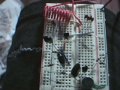
I only built this circuit on a solderless breadboard. I can tap the mic and I hear a taping thru the speakers of the radio. But if I try talking into it it I don't hear anything. I have tried the mic both ways.

Just to make sure though their is 3 green lines on one leg of the mic which are attach to the metal casing so this must be the ground leg going by your advice because the other leg doesn't seem to be attached to the mic caseing in anyway.

And so everybody knows I am working on this circuit
http://www.reconnsworld.com/transmit/fm_trasm.gif

So I can hear tapping thru the speakers so what could it be? if it truely is just that I have to trim the legs to fit tightly together I want to be positive. So I am holding off on this until the last resort. I thought I would eventually get it to work on a solderless breadboard before making it permanant.

The solderless breadboard is plastic so I would think it would work on this even if it doesn't work on a soldered breadboard.

Before I go any further I need to know what the difference between a PCB
or a small stripboard or solderless breadboard or soldered breadboard is?

Tommarrow I will plot the RF waves of the taping by plugging in my radio into my computer audio port.

But other then that I have know clue?
Maybe the graph will shed some light on the issue.

Does it matter if the condensor mic is omindirectional or unidirectional?

The only thing other then what we covered so far is the 4 - 40pf trimmer capacitor and 4.7pf capacitor.
I don't have these parts but I am wondering if using a 4 or 5 1pf in parrell for the 4.7pf and using different fix capacitor sizes for the trimmer is going to screw the whole thing in some way?
None of the items seem to need to be to precise and I don't think I would hear perfect tapping with no noise if I wasn't tuned in correctly. So if the 2 capacitors are not to much of the issue then I would say either I have a transistor in backwards or the components need to be trimmed and put closer together.

It is not the battery it is new and I checked it.
It maybe the mic I will try the mic out somewhere else as well as try a different one. But I really don't think this is it either. Unless I need some special mic which I don't think I need going be everything I read about mic's.

But maybe electert something totally different then a condenser mic?

 
Last edited:

Thread Starter

Mathematics!

Joined Jul 21, 2008
1,036
Just a Recap and a audio/picture clip

The attached picture is what my circuit looks like if this provides anybody with any more info, I was building it on (solderless breadboard)

Note the components are not trimmed but I made sure every component was not touching something they where not suppose to touch. Also note you cann't see the battery or the antenna but I am using a 10 to 12 in antenna and a NEW 9volt alkaline battery.

The zip file contains the audio clip of the microphone taps.

I am wondering if it is truely the spacing and nontrimming of the components that is screwing up the voice. Like you said. But if That was true wouldn't you not hear the microphone taps as well?

I didn't find much of anything out by graphing the RF waves.
Maybe I will give it a better shot with some computer software that acts like an ossiliscope.

But in the end I can only thing that it is either a transistor that is backwards which I am still looking into how to tell for certain.
Or
Spacing of the components (like you said but I am wondering Shouldn't I still hear a little of my voice even if their is alot of noise in this case?)
Or
lack of the 2 capacitors 4.7pF and the trimmer capacitor.
(This could make it easier for me to tune into a station but I don't think this is the major problem since I can make more coils or put things in parrell etc to make almost any desired thing. And most of these components didn't need to be precise even in the specifications on the circuit digram page But maybe I am wrong?)

But it seems with this formula 1/2*pi*sqrt(LC) and a little squeezing of the inductor coil I can tune into any FM station and verify my taping. Seems to work on most of the FM station if I change the desired capacitor (i.e the one for the missing trimmer ) currently I am using 10 pf for it and I am tuned into 105.9 FM.


My main objective tommarrow is to figure out if I have the 2 transistors position correctly. I am 99 % sure they are but being a 100% would narrow the problem down to either 2 of the 3 possiblities.

The microphone looks good to me I tried different microphones same thing.
And I don't think I need a special microphone?

So if it is not one of the things I stated then wtf.
 

Attachments

Last edited:

deepak007

Joined Sep 30, 2007
59
so you have been putting all the components on a bread board(solder less). IT WILL NOT WORK.for any RF project, if the leads are long,they act as antennas.and also they will introduce STRAY CAPACITANCE AND INDUCTANCE.it will change the operating frequency.don't expect that to work.
first rule in rf construction is no breadboards.

this is how you should construct :

http://www.cie-wc.edu/fmtransmitter.asp

http://anarchy.translocal.jp/radio/micro/howtotx.html

how do you plot the waves? do you have a software.the circuit oscillates at 100Mhz.the wire you use to connect the circuit to the computer will act as an antenna and the wave form will be different.
 

Attachments

deepak007

Joined Sep 30, 2007
59
i heard the recording. i think the first transistor is not working well. change the first transistor. i.e audio amp amplifier stage is bad.

next ,increase R1(10k) resistor to 56k or 68k and see. and also check C1 capacitor.or replace it with 22nF.(with the numbers 223 stamped on it)

it should work fine.
 

Thread Starter

Mathematics!

Joined Jul 21, 2008
1,036
rf construction is no breadboards
Then I have to make the components permanent no matter what?
I didn't want to do this first off because one mistake and I am sent back to radioshack to pick up more boards and components to replace the used ones. But if this is the only way then this is the only way.
I am wondering before I start doing this if I could just use my solderless breadboard and just trim the component legs and put them closer would that be ok. Yes/NO? (would it work)

Because I wanted to be sure I got it correct before soldering it up.

I have been practicing soldering and I am pretty good at soldering a wire into a hole on the board but I am unsure what the best way to solder 3 or 4 component legs together should I twist them all together and then appy solder. Or should I try to make a line with the solder to each soldered leg that must be electrically common.

The picture that was in your link seems to look like the latter.
Any suggestions on the easiest, best , and least error prone way of connecting multiple legs togther.

Note I never tried laying a solder line down. This seems like it could be difficult. Suggestions?

Also is their any way or any free software out their that would allow me to build this circuit on the computer and simulate it.

I am just learning LTspice IV but their is no mic component and I am unsure if you can some how, have it beable to talk into a mic and it will graph the carrier frequency with the modulated data ...etc
I.e simulate the RF transmitter circuit.

Also the lack of a 4.7pf and a trimmer is not going to be a problem when I try and build the circuit on a PCB and replace it with a different components instead?

If everything you are saying is correct then after I check the transistor's to be in the correct postion.

And after I am done soldering (provided I don't screw up the soldering) It should work fine.

Man if you are right then it is sort of amazing how much STRAY CAPACITANCE AND INDUCTANCE can screw things up completely. WOW

I am going to hold my breath though.

Thanks for your help so far you taught me a lot.
 

deepak007

Joined Sep 30, 2007
59
are you an engineering student? mind telling me what you do?

take a look at this video.

http://www.youtube.com/watch?v=_uQNRy4s9EU&feature=related

use the leads itself as the tracks and solder,as shown in the video.

begin with small projects and move up. or first purchase a kit,which is cheaper and learn to solder properly.you can find some simple kit projects at fair radio sales,ohio.

build anything ,it doesn't matter what,but practice soldering.after your skills are topnotch you can get anything to work.
it took me two years to get the transmitter circuit to work.nobody helped me,when i needed help. i set out self taught.and don't worry,i will help you build it.
 

deepak007

Joined Sep 30, 2007
59
do one thing.take a signal injector (multimeter has a test signal mode)and inject an audio signal at the base of the second transistor and tune the fm radio. if you can hear the signal, then the first transistor is bad. or the coupling capacitor C1 is bad.
 

Thread Starter

Mathematics!

Joined Jul 21, 2008
1,036
Ok , I will figure the transistor. But I did post an earlier picture of my multimeter. It had the hfe reading E B C E holes I was wondering if I could use these for a quick check. Since the NPN transistors said they had an hfe of 100 (min). One way I put the legs in I get some low number like 15 or so the other way I get 250 which is over 100. Just curious is this the actual hfe reading. My dial is set on NPN as it should be.


(multimeter has a test signal mode)and inject an audio signal at the base of the second transistor and tune the fm radio. if you can hear the signal, then the first transistor is bad. or the coupling capacitor C1 is bad.
On my multimeter is the test signal mode next to the NPN mode it looks like a diode that has a sound wave coming from it. See my multimeter picture earlier posted. If this is correct then where do place the ground probe and the red VCC probe. Do I place the red on the base of the second transistor and the other one to ground?

ALso for the board can I use a Prepunched Perfboard note this board has no small shine copper around any of the holes. But I am running low on the copper hole ones. I have radioshacks 276-1396 it is a pretty big board but I am think of cutting it into smaller piece's . So I have many little boards I can use?

Are the copper hole ones the only ones to use or are they equal good.
I am wondering if the none copper holed boards, Means you need to buy flux. I never really used additional flux was able to just tin the tip flick the little round solder ball of the tip and then touch one side of the components leg with the tinned tip and the other side of the component with the solder. After that the solder just melted to the metal creating a small cone shape. I always take the solder away from the component before the soldering iron and wait few seconds for it to cool.
I never touch solder directly to the iron only in the case of tining the tip.

That last stuff was a recap on how I solder it just works this way the best for me so far. But I have only been soldering wire's into holes. I never tried making many components/wires electrical common. Is this just done by applying more solder so it overflows onto the next hole. Or do you drag some solder from one hole to another to bridge components. I have seen some people twist the legs together in the case of a few components but I don't think this is the best way to do it if you have alot of components.

I don't know what the best way to go about it.
Since the components are going to be close together I would think it is very easy to have solder bridge an unwanted component when trying to bridge another component.

----------------------------------------------------------------------
Calculations for the carrier wave (i.e the FM station being transmitted on )

Assuming 8 to 10 turns L1 = 0.1uH C = 10pf for the trimmer capacitor
1/2*pi*sqrt(0.000000000010 F * 0.0000001 H) =159154943.09189533576888376337251

This means if I use 10pf for the trimmer I would have to tune into FM 159.1 MHZ

And if I used 22pf I would tune into 107302240.74290095656815619177598 = 107.3 MHZ

And if I used 40pf I would tune into 79577471.545947667884441881686308 = 79.5 MHz

The higher the picofard the lower the MHz but in theory I could transmit on any FM station I choose correct? So the trimmer would be just their to allow you to switch channels easily if you use a fix capacitor their is no difference in quality just that it can only use one channel.


As for the 4.7 pf can I just use 4, 1 pf. I have an old TV would this have any 4.7 pf. I still don't know what the 4.7 pf is for in the RF transmitter circuit. Like what is it's job.

The 4.7 is the only thing that I am questioning about before I start trying to solder it up. <- That and how to bridge components without bridging the wrong ones. As well as if the perfboard is ok to use?

Also I am using resistor with a tolerance of gold so they have 5% tolerance. I don't have any 1% tolerance's is this going to matter?
And I am using 1/8 watt resistors, I think 1/8 watt resistors with a 9 volt battery is ok ? But if not I have them in 1/4 or 1/2 watts I believe.

As for my major I graduate with a Masters in Pure Math and a computer science degree. I have always been pretty good with physic's and now I am getting into engineering both electrical and mechanical.

Thanks again
Please let me know if my knowledge of figuring the carrier wave (resonanting frequency) and other things so far is missing anything.
 
Last edited:

deepak007

Joined Sep 30, 2007
59
4.7 pf is for positive feed back to get sustained oscillations.without it it can only be an amplifier,not an oscillator.have you seen the video on soldering?
you can use any general purpose pcb.
if you can calculate the resonant frequency of the tank circuit,then you can use fixed capacitors.no need for a trimmer.
you can use 1/8watt resistor.

as for the soldering on perf board.read this

http://itp.nyu.edu/physcomp/Tutorials/SolderingAPerfBoard
 

Thread Starter

Mathematics!

Joined Jul 21, 2008
1,036
4.7 pf is for positive feed back to get sustained oscillations.without it it can only be an amplifier,not an oscillator.have you seen the video on soldering?
So can I still use 4 or 5 pf instead of 4.7pf?

And yes I saw the video thanks.

I found out that one of my components a capacitor C1 one of it's legs is out of place I connected where it should be. And now on the Solderless Breadboard I can hear my self on the radio around 159.1 Mhz Fm.

The audio clip is attach in the zip file.

It is very noise but you can make out the voice. What do you think I am saying?
The clearest transmission I got was when it was completely squeeky in the background no sizzely. <--(did not record this one.)

I believe everything is where it should be now what I am wondering is since it is a solderless breadboard is that the reason why the voice is so crappy or is it the substitution of the 4 1pf instead of the 4.7 pf the main reason.

Me, being a mathematician cann't fully believe it is going to be any different on a PCB ,...etc then a solderless breadboard. If I trim the components so they fit really close together on the solderless breadboard. I cann't see it being any better quality on the PCB breadboard ones. Where would it be getting it's better quality from. On both of them you can put the components close together with no excess legs showing. The only thing I can think of is that the power strips could act as 2 seperate anntena. But I still don't think this is a major interferance problem?
So where is all the stray capacitance/inductance going to come from if the legs are trimed and components are tight on the solderless board?

This is why I think the interference has to do with the 4.7pf being 4 or 5 pf instead?

So my big concern is the importants of having a 4.7 capacitor? Which I do not have. Wondering if their is one in the old TV I have who knows maybe even a 4-40pf trimmer cap is in their? Because if I get to the end of soldering everything and it sounds like crap and only transmits 3 ft because of the lack of 4.7 pf that would suck.

I am sorry but I didn't quite get what the purpose of the 4.7pf is ? Is it part of the tuning ossilator or part of the modulation or part of some amplification?

I should have mention that the radio I am using is a shit 1980 walkman but that is all I had to test the recieving end with.
So maybe the interferance may partly be because of that. I will try the car radio ofcourse I cann't record from the car to post the wav file of it but I will let you know if it is much better.

At least I am getting closer.
Waiting for the answers to this post to move forward.

Thanks this is cool
 

Attachments

Last edited:

deepak007

Joined Sep 30, 2007
59
CHANGE the resistor R1 to 56k or 68K. and that should work ok.the circuit uses 10k,but that will introduce distortion.

you can use 4 1 pf's in parallel. its no prob.

if the disturbance is still present,then you are tuning it to a harmonic frequency.

actually this kind of transmitters have to be constructed on a pcb with tight layout,and should be enclosed in a metal box to prevent interference.

you need to know more about the transmitter theory. that is why PLEASE READ the description of the wasp. it has each and every point covered regarding the 4.7pf, interference and many more.if i were to explain it,then i need to type three or four full pages of theory.

but,i will explain some important points.

the leads or wires you use to connect the 9v battery may be the culprit.because, in any circuit,if you use lonf wires, the 60hz mains hum or some kind of rf signals gets induced in those wires.at rf any small lead or wire will work as a receiving antenna.
then these rf signals are coupled into the transistors and amplified. the result is hiss or noise.

remedy? (this is covered perfectly in wasp theory)use a supply decoupling capacitor. use a 22nf (223 stamped on it) across the positive and negative rails. then there will be no hiss.

the circuit you are trying to build has many mistakes.the designer did not design it properly. that is why i suggested you some other circuit.


what kind of fm receiver are you using? because 159 Mhz is not present in ordinary fm walkman .right?

when you solder the circuit the frequency may change again.
 

Thread Starter

Mathematics!

Joined Jul 21, 2008
1,036
Thanks for the clearing up of the 4.7pf. I wil get back to you when I throughly read thru your links.

However I would like to see the initial circuit work before moving on to the WASP one. Since the audio clip is from the initial circuit I was trying to make which seems like I am making progress with it. Just have to find why the interferance if the components are trimmed? What do you mean by harmonic frequency 159.1MHz. I realized this isn't a good value to choose anyway. I will change it to a different station.

As for the solderless breadboard if I cut the battery clamp wires so they are the shortest they can be then I should not get any interferance (or alot less). Not Any more then I would get from the PCB board. Since all the components are almost as tight as the pictures of a PCB circuit on my solderless breadboard. Legs trim ,tight , ...etc.

Even better it is plastic which is a good insulator and I can definitely put it into a plastic tiny box. So where could be the interference , stray conduntance /inductance ,..etc???????

At least I don't see the big difference in interferenc between the 2 board types?

I will change the resistor and add a capacitor like you said don't have 22 nf pf or uf is their another substitute?

Thanks and sorry if I am repeating myself. Maybe when I read thru your WASP links it will answer these questions about the original circuit I am working on.
 

deepak007

Joined Sep 30, 2007
59
you said that you have 10nf(.01).use two of them in parallel. solder them across the positive and negative terminal of the battery.that will get rid of the hiss or noise.

harmonics?

a friend of mine explained harmonica as :

" Have you ever "BLOWN" into a harmonica? It emits all kind of sounds right? Well so does an RF transmitter. Not a defect or a fault of the transmitter itself, but a byproduct of all radio frequency transmitters and oscillators. When it transmits on any particular frequency it has been designed for, it is also transmitting on a lot of other frequencies, usually lower or higher that the actual frequency you have tuned it at."

the one that you are building is a fm transmitter which transmits in fm band(88-108Mhz). but,you are intercepting it at 159Mhz.it may be a harmonic of fm band.so,you will not get the signal properly.you have to tune your radio in fm band.by the way, are you using a VHF HI BAND receiver?
 

Thread Starter

Mathematics!

Joined Jul 21, 2008
1,036
Ya, the harmonics was probably from be computer speaker. I was using it to broadcast some music to my walkman. It worked but very bad quality.

Anyway I will try the capacitors, yes I have the 10nF ones.

159Mhz This frequency was probably a bad choice.

I figured that 30pf gives 91888149.236965341585221083052271 = 91.8Mhz

and if I make 31 pf gives me 90393933.407960091398541261690557 = 90.3MHz . Which is a station you can dial into on a radio.

I am wondering if the latter is a good choice to use for the frequency.
I mean is it better to use a lower station in the 80 or 90 MHz range or higher?

In theory it won't matter which one as long as it is a statiion that you can dial into on your radio reciever. Which I don't think 159MHz was one of them anyway.

If I use a station say I tuned it exactly for Rock 102 when I transmit would I hear my voice and rock 102 music together or will all the radio's in the 1/4 mile just hear my transmision and not rock 102. I would think they would hear both? But would my signal be still to weak to hear over the music playing on that station?

Since I don't have a trimmer what size capacitor do you think I should use i place of it


This is probably why it is better to use a lower station because I don't hear much stuff being broadcast on the lower 88 Mhz. Anyway I am going to attempt to build it permanent today. Let you know how it comes out.
Latter I will have some questions about extending it to farther range.

I already know how to figure out the optimal antenna size for a given frequency channel. So the only last stuff to learn for the transmitter end is how to make the wave travel a farther distance and how to make the quality better.

I am assuming that the transmitter part is usually easier to build then the reciever? Because you have to not only tune and demodulate but also amplify and possible filter the sound before sending it to a speaker.

The transmitter only has to modulate a carrier wave and send it on it's way.
 
Last edited:

deepak007

Joined Sep 30, 2007
59
you are right about the receiver.

you can tune the bug to 88Mhz to avoid the interference from other fm stations. your transmitter is not a powerful one,but it might interfere with other stations.actually,the commercial stations are powerful.so you cannot jam them,but can only cause interference. the receiver will respond to only high power signals.it depends upon on the signal strength.

think of it this way,if you are talking to your friend, and at the same time, some one else shouts at the top of his voice , your friend may not understand what is happening.the same may happen here.you may not get anything but disturbance, if you tune at rock 102 ,with your transmitter turned on.

as for the capacitor, any size will do.
 

Thread Starter

Mathematics!

Joined Jul 21, 2008
1,036
Ok, I kind of thought that was what would happen. Another example is cross talk from the POTS phone service. Sometimes you may have crossed lines that pick up another conversation while you are talking. This can get hard to talk through.

as for the capacitor, any size will do.
But I thought it depends on the 1/2*pi * sqrt(LC) for the carrier frequency (i.e the station frequency) Obviously I would want to tune it to a station that is usually weakly broadcasted. Is this why they said turn it to 88MHZ in the sizzy and adjust the trimmer capacitor until you get the best quality. Because I think if you adjusted the trimmer to rock 102 station it would probably be hard to hear it if anything non matter how good the quality of the RF circuit you built.
You would have to make your transmitter over power the stations or come a little closer to their power level
to actually be the domnant station broadcaster.

I am still a little puzzled by what makes your transmitter broadcast farther distances (i.e cover high distances).
In FM modulation you vary the frequency so increasing the voltage just increases the amplitude but the higher amplitude how does this make the signal stronger? The frequency doesn't really change. I mean I could see this helping in AM amplitude modulation but FM?

Because the only thing you can increase in a circuit is the voltage or current. What makes FM station broadcast farther.
Is their any mathematical way of figureing this out?

Maybe it is not so much the current or voltage but the speed at which you modulated the carrier in FM? Which is effected by how fast the current voltage (power is). But I don't think this is it because if you modulate the same carrier wave at a faster rate you are changing the voice signal.

Or maybe it has to do with the stength of the propagating eletromagnetic field comeing off the antenna. I bet that is it and the more current , voltage , power ...etc produces a stronger electromagnetic field coming of the anntena. Which doesn't die out as fast as a weaker strength electromagnetic field.


If you don't tune it for a station that isn't strong then you are going to be doomed with interference from the station. Right?

Also instead of using 5 1pf for the 4.7 pf I am going to use 2 10 pf in series. Is this OK 1/(1/10 + 1/10) = 1/(2/10) = 5pf.
I can do the math just wondering if their is anything in radio theory that makes in series capacitor more prone to interference then in parellel.
I would think using less capacitors to make the desired capacitance is always probably better since their is probably some tolerants in the capacitors. And the sum of the tolerances of more capacitors is probably a little more then the sum of fewer in general.
 
Last edited:
Top