Radio transmitter problem

Thread Starter

Mathematics!

Joined Jul 21, 2008
1,036
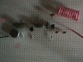
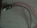
Ok , got all the components layed out on the perfboard. I am probably going to move some of them closer together.

See the pictures.

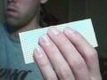
WOW breaking my big perfboard into a small one was a little painful.
You cann't cut it with sizzors or a knife. I had to hang it over a table edge and use a lot of force to break out a smaller board piece. Is their any tool that makes this easier?

Anyway The small board I am going to but it on is a 17 hole by 37hole board. I could have made it a little smaller but I wanted a little extra room just in case I need it. (this is my first permanent circuit )

As you can see in the pictures maybe, Their is NO copper surrounding any of the holed. I am wondering if these types of boards are going to be harder to solder then the ones with the copper surroundings. What exactly is the copper surroundings purpose. Is it to keep the solder from going to the next hole?

Anyway before I make this permant I am going to pratice with these types of boards. Is it nessary to by flux I never used it just what the solder has in it and a little tining of the tip.

Thanks
 

deepak007

Joined Sep 30, 2007
59
capacitor SIZE means, voltage range.there are different sizes. i was not talking about the VALUE.you have to calculate the cap VALUE using formula only.

to transmit further, you need to increase the strength of the signal. this is achieved by using power amplifier stage.

here you don't change the voice frequency,but will only increase the amplitude. think of it this way. if you speak in a normal voice,the range of your voice signal is 10meters. if you want to send your voice signal to 50 meters range. then you have to shout. then the power level is increased and your voice can be heard at 50feet. here you don't change your voice signal frequency,but only the amplitude is increased.all you did was amplification of your voice.
in the same way,the modulated rf power signal is given again to an rf amplifier stage.this will increase the range of the signal.

you can you the series cap combination.

use two 10nf 's in parallel across the positive and negative leads.

actually,there will be copper around the circles,on the back side , on most of the boards.the copper around the circles is to secure the component to the board.it is not necessary.

you can use a hacksaw blade(small) for cutting the board.
 
Last edited:

Thread Starter

Mathematics!

Joined Jul 21, 2008
1,036
actually,there will be copper around the circles,on the back side , on most of the boards.the copper around the circles is to secure the component to the board.it is not necessary.
Yes , but what I was try to get at here is my board doesn't have any on either side. I am wondering if I need to buy flux or can I just use solder like normally. They also sell tip tinner but I always just touched the iron to the solder and flicked the little ball of solder off. I am just making sure their isn't something that I am missing that would make soldering easy.

As for the distance of the RF wave thanks for clearing that up.
So Once you master creating a transmitter and mastering a power amplifier you can pretty much broadcast far distances. Not that I want to do anything illegal here.

Anyway is their a formula to compute how much power is need for a certain range?

And in theory if we lived in a vaccum we wouldn't need a power amplifier sense the RF waves would propagate forever and never dissipate out.
If this is true then what is in are atmosphere/air that effects the RF waves so much that they don't go on forever?

Energy cann't be greated or destroyed so the changing magnetic field induces a change in electrical field on and on forever until something takes the energy away from it ....etc etc
 
Last edited:

deepak007

Joined Sep 30, 2007
59
yes, use flux for a clean soldering. the power and distance depends upon the terrain and atmosphere. if the no of buildings in a area are more,the distance will reduce. also the transmitter and receiver should be line of sight for maximum range.
if there are many water bodies in that area,the range will decrease, for example : trees,human body etc.human body absorbs radiation if the transmitter is worn on the body,it can reduce the range. transmitter works like a micro wave oven. water bodies absorb waves and gets bombarded and heated up. this is just a general concept.technically,the subject is very complex and big.it's beyond me.you have to study ARRL ANTENNA BOOK for more details.
 
Last edited:

Thread Starter

Mathematics!

Joined Jul 21, 2008
1,036
Also about the carrier wave , so using this formula 1/2*pi * sqrt(LC)

With the correct capacitor and inductor I could get any decide carrier wave something in the 2 GHz or microwave or infrared or .,..etc

What I am getting at is that with this circuit just varying capacitor and inductor you can make any resonanting/carrier wave.

Is their any limit on L, C values for the resonanting frequency to work at in a given circuit? Or will this formula always work no matter how small the inductor or capacitor values are?


Then you would just need to make the reciver for that resonanting/carrier frequency correct?

So to make a cell phone transmitter which is in the Ghz range all I would have to do is vary C and L so I tune into one of their carrier frequency. Obviously you still need to authenticate in some way but in theory if their was no authentication then their recievers would recieve your call.

If this is true then why do they stop at GHZ why not faster and faster rates of data transmission what is taking them so long. Maybe their problem isn't going faster for one person but when multiplexing/demultiplexing come into play then they haven't found away to seperate the peoples frequencies at faster rates. Maybe that is it?

O, and I can figure out optimal anttena length but why the different shapes.
Is their any math or theory behind the different shapes of anttena's and what the best shape would be?
 
Last edited:

deepak007

Joined Sep 30, 2007
59
you can use the formula to determine the frequency. but, it also depends uopn the transistor type you are using. if you want to transmit on 1Ghz,first you need to calculate the L,C, values and also you have to use microwave frequency transistors.i.e look for a transistor data sheet, whose Ft is greater than 1Ghz.then you can use it.other wise no.


antenna? there is a lot of math behind the antenna's. you just download any book on antenna's. the concept of antenna's is very big. for an intro read this:

http://www.electronics-tutorials.com/antennas/antenna-basics.htm

have you completed the circuit?
 

Thread Starter

Mathematics!

Joined Jul 21, 2008
1,036
It works fine. Except it doesn't go very far?

Is their an amplifier circuit I can add to it to amplify it before it gets propagated into the air by the antenna?

Also is their anyway to calculate an approximate distance the wave will be recieved by a standard reciever.
Given the power of a the carrier wave can you calculate the approximate distance. Assuming I have the optimal antenna length.

I am wondering how much power (I*V ) gives how much distance for transmission? Typically I know their is alot of factors like how good the reciever is and how congested the RF spectrum is in my area ..etc etc but I am looking for an approx. based on the power.

You can assume I have the correct antenna height for my station
89.1 MHZ.

I am wondering if connecting a ton of 9 volt batteries together would help. But I don't want to burn any components like the mic out?

Thanks for all your help "IT WORKS"

Also I am curious not only with how you calculate the distance of the wave propagation. But why some antennas have different shapes.
I would think the best antenna would be one that is straight up and down about 1/4 the wave period * speed of light.

What does the different shapes do?

Also is their a simple FM radio reciever I can build just for the recieving of this station That I can plug into I computer audio port or speaker?

I want to learn both sides transmitter and reciever side.
I understand it goes antenna , tuner , demodulator , amplifier , speaker or output.
But I am wondering if the tuner can be simplified to just 89.1MHz FM.
Not sure on how to demodulate FM , I know AM uses just a diode?
Not sure on how much and how to amplify the demodulated signal to computer audio card level or speaker level?

Though I am think the reciever should be to much harder. Any help.
 
Last edited:

suntop

Joined Feb 9, 2008
4
Tuned frequency will be f (FM) = 1/(2*pi*square root (LC)) /1Meg ( you get frequency in MHz)


Here ,
pi=3.1415
L is inductance(the Coil) of tank circuit's inductor in micro Henry
C in capasitance(The Trimmer/of a fixed cap what ever you use) of tank circuit's capasitor in pico Faraday.

Using 25 Pf Cap and a 0.1 uH Ind will give almost 100 MHz Broadcasting frequency

If you have a good multimeter that can measuere caps/inds make these capacitors using coins (use paper/polythene/plastic to isolate plates and fix them with tape)
approx 6-8 turns on a pen using the core copper wire of a standard co-axial cable will give you approx 0.1 uH
 

DickCappels

Joined Aug 21, 2008
10,661
Most likely, (if you have the transistor pinouts correct), its oscillating a too low a frequency. The best thing is to get closer to the proper capacitance values, then reduce the number of turns. You can then use finger capacitance across the coil to rapidly tune the transmitter. If, after turning it on, when you press your finger onto the coil, you hear a sound in the receiver (the sound of the carrier sweeping by), then the frequency is too high. Add turns or add capacitance.

The feedback capcitand should really be close to 4.7 pf. Most likely 1 pf is not nearly enough for oscillation at this frequency, and 10 pf would put the resonat frequency too low.

Sometimes this circuit takes some fiddling, but most of the time, the problems are with the RF capacitors and the inductor, so fiddle with those once you are satisfied that the DC voltage readings are within "sane" limits.
 

radiohead

Joined May 28, 2009
514
The key to all basic transmitter circuits is the tank circuit. If you can't pick up the signal on a standard radio, that doesn't mean it's not transmitting, it's likely on a freq outside the range of your radio. Use a wide-band receiver or adjust the number of turns on your coil. Typically, it's around 8 complete turns on a 1/4 inch form (air core). Fewer turns = higher the frequency, more turns = lower frequency. Most of the simple circuits are tuned for the 88-108 band using the 3rd harmonic.
 
Last edited:
Top