I have made this circuit but its signal can not be detected by fm receiver. I used all components exactly the same but its signal cannot be captured. anyone have experience in RF communication to help me out of this circuit please!
try tuning C3 , R4 (? , R5) -- there was a web design/lab that showed an UHF like layout of the PCB -- say -- battery "far" left ..... and L1 + antenna "far" right . . . it also had a minimal RF decoupling of the (supply) battery ?? and further on -- of the RF stage (if i remember right)
Are you using a "condenser" microphone? Is it powered?
The circuitspedia site on my desktop PC showed a BC547 transistor in a TO-92 package next to the circuit. It's pinout is different than the 2N3904 in the same package. Did you use the correct pinout for the 2N3904?
it may also be that the same transistor and package from different year/manufacturer might have different pin assignment - that's why i always measure the hFE or diode junctions (V.BE > V.BC) for the one or some from the "new" set . . . or to verify the desoldered component
then you should be able to tell is Q1 working, which is hopefully the fault.
The Rf side, a bit more of a problem,
no easy way your going to debug that ,
things like this , the layout of bits like C4,5 6 and L1 , is critical,
They are very small capacitance and inductance being used to make a resonant circuit,
this sort of stuff needs careful laying out, it does not work on a Vero or bread board.
When you said "FM receiver" is an FM Brodacast reeiver that tunes in the area of 88 MHz to 108 MHz?
Except when crystal controlled, I have not had much luck getting FM transmitters to operate at the desired frequency without some adjustment, so this is a normal situation.
What several of us want to know is what construction method you used.
If it is on one of those plug-in breadboards the next thing to do is get a small piece of PC board material and re-built it dead bug style.
Somebody once told me that his LED voltage boost circuit works without an inductor. It turns out that he had built the circuit on a plastic plug-in breadboard and it was operating at VHF frequencies using the inductance of the wires used to connect one part of the circuit to another. Such breadboards are often a problem when using fast components, like the 2N3904, which can oscillate at hundreds of MHz. Put your parts a little closer together than shown in the photo above because you will be working with RF around 100 MHz.
Please double-check your components -the pin-outs for the transistors, etc. and when you think everything is right, with a digital voltmeter you can check the base and emitter voltages on Q2 and see if they seem reasonable. If either the base or emitter is very close to one end of the battery or the other, then there is a bad component or a wiring error.
Make sure the capacitors are what the schematic asks for. Sometimes it is difficult decipher the capacitor's markings.
The emitter should be about 0.6 volts less positive with respect to the battery's negative terminal than the voltage on the base base.
The collector should measure the same as the battery voltage (there should be no DC voltage across L1, only sine waves).
If those look right then its time to tweak the resonance to get the thing to oscillate somewhere in the FM band.
The last couple fixed-frequency transmitters I made were tuned by deforming the inductor. But before doing that, place an FM receiver close-by and turn it on. Tune around listening for a place on the dial where the hissing noise go away is either there or greatly attenuated. If it is not a broadcast station, it is your transmitter.
At that point I would tune the receiver up to where you cannot hear any broadcast stations near the highest frequency on the dial and slowly touch the inductor and listen to see if I could hear the transmitter's frequency sweep through the bandpass of the receiver as the distance between my finger and the inductor changes. If the transmitter gets pulled into the top of the FM band by putting my finger close to or in contact with the inductor, that means that you have to either increase the capacitance across the inductor or add more turns to the inductor.
You can slightly increase the capacitor values or add turns to the coil.
If you were unable to hear any effect of your transmitter then your trasmitter is probably oscillating at a frequency below the FM band and tune the receiver to a spot near the low end of the band where you cannot hear any broadcast stations and try stretching out the inductor to raise the transmitter's frequency.
Replace C-5 and C-6 with a single 5-30pF trimmer capacitor. Replace C-3 with a 47pF disc. Replace L-1 with a fixed value .1uH ferrite core inductor. Replace C-4 with a 4.7pF disc. Move the antenna and 10pF capacitor off of the collector and attach to the emitter. This will reduce the range a bit but increase frequency stability. When adjusting the trimmer, use a non-metallic (usually nylon) RF trimmer tool. Once it is up and running, I will show you how to add an RF amplifier to increase range a lot.
Prepare your Receiver and a multimeter and set the range to AC 10V or 20V, and in series with an 0.1uF capacitor without polarity, and now you can do a test with the other pin of capacitor on Vc_Q1, Vb_Q2, Vc_Q2, and the other Probe connecting to Ground, when you do the test then you need to hit the Mic.
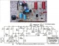
I am in doubt also because I downloaded two datasheet for 2n3904 and 2n2222 but they are different. that's my circuit, I use heavy DPC for power boxView attachment 210767
When you said "FM receiver" is an FM Brodacast reeiver that tunes in the area of 88 MHz to 108 MHz?
Except when crystal controlled, I have not had much luck getting FM transmitters to operate at the desired frequency without some adjustment, so this is a normal situation.
What several of us want to know is what construction method you used.
If it is on one of those plug-in breadboards the next thing to do is get a small piece of PC board material and re-built it dead bug style.
Somebody once told me that his LED voltage boost circuit works without an inductor. It turns out that he had built the circuit on a plastic plug-in breadboard and it was operating at VHF frequencies using the inductance of the wires used to connect one part of the circuit to another. Such breadboards are often a problem when using fast components, like the 2N3904, which can oscillate at hundreds of MHz. Put your parts a little closer together than shown in the photo above because you will be working with RF around 100 MHz.
Please double-check your components -the pin-outs for the transistors, etc. and when you think everything is right, with a digital voltmeter you can check the base and emitter voltages on Q2 and see if they seem reasonable. If either the base or emitter is very close to one end of the battery or the other, then there is a bad component or a wiring error.
Make sure the capacitors are what the schematic asks for. Sometimes it is difficult decipher the capacitor's markings.
The emitter should be about 0.6 volts less positive with respect to the battery's negative terminal than the voltage on the base base.
The collector should measure the same as the battery voltage (there should be no DC voltage across L1, only sine waves).
If those look right then its time to tweak the resonance to get the thing to oscillate somewhere in the FM band.
The last couple fixed-frequency transmitters I made were tuned by deforming the inductor. But before doing that, place an FM receiver close-by and turn it on. Tune around listening for a place on the dial where the hissing noise go away is either there or greatly attenuated. If it is not a broadcast station, it is your transmitter.
At that point I would tune the receiver up to where you cannot hear any broadcast stations near the highest frequency on the dial and slowly touch the inductor and listen to see if I could hear the transmitter's frequency sweep through the bandpass of the receiver as the distance between my finger and the inductor changes. If the transmitter gets pulled into the top of the FM band by putting my finger close to or in contact with the inductor, that means that you have to either increase the capacitance across the inductor or add more turns to the inductor.
You can slightly increase the capacitor values or add turns to the coil.
If you were unable to hear any effect of your transmitter then your trasmitter is probably oscillating at a frequency below the FM band and tune the receiver to a spot near the low end of the band where you cannot hear any broadcast stations and try stretching out the inductor to raise the transmitter's frequency.
Are you using a "condenser" microphone? Is it powered?
The circuitspedia site on my desktop PC showed a BC547 transistor in a TO-92 package next to the circuit. It's pinout is different than the 2N3904 in the same package. Did you use the correct pinout for the 2N3904?
Circuitspedia.com is from a country that posts circuits that .... well, look for yourself.
On another website there was the same or a similar circuit and it had 4 problems:
1) Its audio preamp transistor was saturated when the battery was new and was cutoff when the battery was old.
2) Its radio frequency changed as the battery voltage ran down.
I fixed both problems by using a 5V low dropout voltage regulator.
3) Its radio frequency changed when something moved towards or away from its antenna. I fixed it by adding an RF amplifier transistor that isolated the oscillator from the antenna.
4) It sounded muffled with no high audio frequencies. I fixed it by adding the pre-emphasis (treble boost) used by all FM radio stations and it matches the de-emphasis used in all FM radios.
I built mine compactly soldered together on stripboard. It will not work if made on a solderless breadboard.
Its range is very far to a good quality home stereo or car radio.
 Facebook
 Google
 GitHub
 Linkedin