Facebook
 Google
 GitHub
 Linkedin
Hi, I hope all members are doing well.
I would like to ask a couple of of questions regarding look up tables.
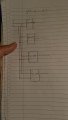
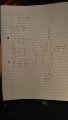
1) how can we create 2-1 multiplexer using only 2 input look up tables?
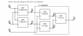
2) can outputs of one set of look up tables be used to map SRAM bits of another look up table?
Any help is much appreciated.
I would like to ask a couple of of questions regarding look up tables.
1) how can we create 2-1 multiplexer using only 2 input look up tables?
2) can outputs of one set of look up tables be used to map SRAM bits of another look up table?
Any help is much appreciated.