Facebook
 Google
 GitHub
 Linkedin
Hi all!
I'm working on a hobby LLC resonant converter and I'm having issues with picking capacitors for the resonance capacitance C_r.

(Picture from https://www.researchgate.net/figure/Half-Bridge-LLC-resonant-converter-configuration_fig9_261419357)
Here are the specs/requirements have:
V_in adjustable up to 60V. (my PSU has max 60VDC)
Roughly 300W max power.
Half-bridge, max switching frequency of 500kHz.
L_r is meant to be purely leakage inductance of the transformer. This can always be adjusted in my case, the air gap can be changed (rotary transformer).
The transformer is not yet wound, so this converter will be adjusted according to L_r and L_m.
Trafo ratio will be 1:1.
Load resistance R_L is fixed at 2.2 Ohms.
Output current i_L max 15A, but it's OK if it only reaches 10A in the end (hence 300W to get some headroom).
C_F is adjustable.
I've gone through the design guide from Infineon, and something like m = 5 and Q = 0.75 look alright to me. Note that these are just "desirable" values, as long as it's not a "sharp peak" at the resonance frequency (f_r) I'm fine. The plan is to switch atleast at f_r, and increase the frequency to decrease the output current. I don't have a requirement to be able to adjust all the way down to 0.1 voltage gain, if I am only able to go between 1.0 (f_r) and 0.5 (max frequency) this is fine. If this range is not able to decrease the current enough, I'll just decrease the input voltage. If it's possible to adjust the output current between 7A and 12A, that will be sufficient. I really have to stress that these "requirements" are not strict!
Here's an example set of values:
m = 5 (inductance ratio)
Q = 0.75 (quality factor)
=>
C_r = 1.1 uF (resonance capacitance)
L_r = 2 uH (leakage inductance of trafo)
L_m = 8 uH (mutual inductance of trafo)
=>
f_r = 106 kHz (resonant frequency)
Here's the calculated gain curve with respect to frequency for these component values:

This is assuming that the rotary trafo with its ferrite cores (pot core) reaches 2uH leakage and 8 uH mutual. The ratio between leakage and mutual can always be increased by adjusting the air gap, but the inductances themselves are determined by the cores and number of windings. From my calculations with the ferrite cores I have ordered, the trafo should get roughly 3uH leakage, 10 uH mutual with 1 mm air gap and 6 turns. Here is the script, please take a look! I have never worked with reluctance calculations before. The primary and secondary cores are both of this sort, and they are facing eachother.


The formulas stem from this paper:


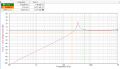
Let's say I want the inductance ratio to be between 4 and 6, that would mean that the air gap could be set to within the dashed lines:

Does this plot look reasonable?
I assume that h_wp = h_ws is the "winding depth" (9mm). I adjusted N=Np=Ns to reach the desired inductances, but 6 turns sounds extremely low. Any issues with this?
The reason I want the trafo inductances L_r (L_lk) and L_m in the order of a few uH, is because the resonance capacitance C_r gets around 1 uF. This means that I'll be able to use a few 0.2uF MLCC C0G caps in parallel. From what I have read, these seem perfect for this application due to their stability in capacitance. However, the problem arises if the trafo inductances get too big after I've wound it e.g. L_lk = 20uH, L_m = 100uH. That would mean that I need C_r = 11.2uF to arrive at a similar voltage gain curve, which would require 56 caps in parallel. I plan on having more footprints than I need so that I always can adjust the capacitance by soldering on/off more caps if needed. However, 56 caps of that sort would be unnecessarily expensive, and also very wide on the PCB. Also, the resonance frequency decreases to 10.6 kHz.
An alternative to MLCC C0G caps are PP-film caps. Specifically Pulse Film caps that can handle AC. Here's and example. These would make it really easy to reach capacitances above 10uF, but I am unsure about some aspects. If a capacitor is rated for a voltage derivative of e.g. 200 V/us, how do I know if the square wave from the half-bridge is not ruining the cap? When the applied voltage over the cap goes from 0V to 60V, you only really have to worry about the rise/fall time of the MOSFETs, no? The MOSFET I am planning on using has a fall time of merely 4.7ns, which means roughly (-)13000 V/us (60V to 0V in 4.7ns). Am I thinking of this correctly? I feel like I am missing something.
Thoughts?
I'm working on a hobby LLC resonant converter and I'm having issues with picking capacitors for the resonance capacitance C_r.
(Picture from https://www.researchgate.net/figure/Half-Bridge-LLC-resonant-converter-configuration_fig9_261419357)
Here are the specs/requirements have:
V_in adjustable up to 60V. (my PSU has max 60VDC)
Roughly 300W max power.
Half-bridge, max switching frequency of 500kHz.
L_r is meant to be purely leakage inductance of the transformer. This can always be adjusted in my case, the air gap can be changed (rotary transformer).
The transformer is not yet wound, so this converter will be adjusted according to L_r and L_m.
Trafo ratio will be 1:1.
Load resistance R_L is fixed at 2.2 Ohms.
Output current i_L max 15A, but it's OK if it only reaches 10A in the end (hence 300W to get some headroom).
C_F is adjustable.
I've gone through the design guide from Infineon, and something like m = 5 and Q = 0.75 look alright to me. Note that these are just "desirable" values, as long as it's not a "sharp peak" at the resonance frequency (f_r) I'm fine. The plan is to switch atleast at f_r, and increase the frequency to decrease the output current. I don't have a requirement to be able to adjust all the way down to 0.1 voltage gain, if I am only able to go between 1.0 (f_r) and 0.5 (max frequency) this is fine. If this range is not able to decrease the current enough, I'll just decrease the input voltage. If it's possible to adjust the output current between 7A and 12A, that will be sufficient. I really have to stress that these "requirements" are not strict!
Here's an example set of values:
m = 5 (inductance ratio)
Q = 0.75 (quality factor)
=>
C_r = 1.1 uF (resonance capacitance)
L_r = 2 uH (leakage inductance of trafo)
L_m = 8 uH (mutual inductance of trafo)
=>
f_r = 106 kHz (resonant frequency)
Here's the calculated gain curve with respect to frequency for these component values:
This is assuming that the rotary trafo with its ferrite cores (pot core) reaches 2uH leakage and 8 uH mutual. The ratio between leakage and mutual can always be increased by adjusting the air gap, but the inductances themselves are determined by the cores and number of windings. From my calculations with the ferrite cores I have ordered, the trafo should get roughly 3uH leakage, 10 uH mutual with 1 mm air gap and 6 turns. Here is the script, please take a look! I have never worked with reluctance calculations before. The primary and secondary cores are both of this sort, and they are facing eachother.
The formulas stem from this paper:
Let's say I want the inductance ratio to be between 4 and 6, that would mean that the air gap could be set to within the dashed lines:
Does this plot look reasonable?
I assume that h_wp = h_ws is the "winding depth" (9mm). I adjusted N=Np=Ns to reach the desired inductances, but 6 turns sounds extremely low. Any issues with this?
The reason I want the trafo inductances L_r (L_lk) and L_m in the order of a few uH, is because the resonance capacitance C_r gets around 1 uF. This means that I'll be able to use a few 0.2uF MLCC C0G caps in parallel. From what I have read, these seem perfect for this application due to their stability in capacitance. However, the problem arises if the trafo inductances get too big after I've wound it e.g. L_lk = 20uH, L_m = 100uH. That would mean that I need C_r = 11.2uF to arrive at a similar voltage gain curve, which would require 56 caps in parallel. I plan on having more footprints than I need so that I always can adjust the capacitance by soldering on/off more caps if needed. However, 56 caps of that sort would be unnecessarily expensive, and also very wide on the PCB. Also, the resonance frequency decreases to 10.6 kHz.
An alternative to MLCC C0G caps are PP-film caps. Specifically Pulse Film caps that can handle AC. Here's and example. These would make it really easy to reach capacitances above 10uF, but I am unsure about some aspects. If a capacitor is rated for a voltage derivative of e.g. 200 V/us, how do I know if the square wave from the half-bridge is not ruining the cap? When the applied voltage over the cap goes from 0V to 60V, you only really have to worry about the rise/fall time of the MOSFETs, no? The MOSFET I am planning on using has a fall time of merely 4.7ns, which means roughly (-)13000 V/us (60V to 0V in 4.7ns). Am I thinking of this correctly? I feel like I am missing something.
Thoughts?
Attachments
-
 54.8 KB Views: 3