 Facebook
 Google
 GitHub
 Linkedin
Have got this new device.
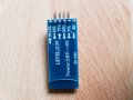
Should be a HC-06 BT.
https://www.trab.dk/da/breakout/155-hc-06-bluetooth-serial-pass-thru-module.html
As seen on my photo it says Power 3,6-6V. and that is ok for my 16F18877 ( 5V )
but the levels for signal says only 3,3 V,, how could i fix that ?
Should be a HC-06 BT.
https://www.trab.dk/da/breakout/155-hc-06-bluetooth-serial-pass-thru-module.html
As seen on my photo it says Power 3,6-6V. and that is ok for my 16F18877 ( 5V )
but the levels for signal says only 3,3 V,, how could i fix that ?
Attachments
-
 136.1 KB Views: 3
 -
 141.1 KB Views: 3


