Question about Voltage Drop

Thread Starter

WakelessFoil

Joined Apr 16, 2020
12
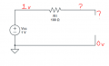
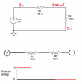
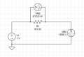
I am trying to use a potentiometer to drop voltage. I just learned about resistors and voltage drop so I thought that if I supply an input voltage I can reduce it using the pot. But when I attach my volt meter on the other side where my load/output would be I get VCC? Can someone help me understand this conceptually? I am not interested in understanding electronics by memorizing rules rather than actually grasping what is going on!
 

Attachments

WBahn

Joined Mar 31, 2012
30,045
Your voltmeter has a very high (ideally infinite) resistance, so the total current in your circuit is zero, meaning that the voltage drop across your resistor is zero.

Your meter across the resistor is showing 512 nV which, across 512 Ω, is a current of 1 nA. That would indicate a meter resistance in the 1 GΩ range. I'm assuming these numbers are from a simulation of some kind? Typical real meters have resistances in the 10 MΩ range, give or take an order of magnitude.
 

MrChips

Joined Oct 2, 2009
30,794
The one rule that you must learn and memorise is Ohm's Law.
This is stated as
I = V / R

The two corollaries are
V = I x R
R = V / I

Without this knowledge you are going nowhere fast.
You use Ohm's Law in order to understand how voltage dividers and potentiometers behave.

1667667652339.png

When you apply a load, or even a test meter, you alter the circuit. You need to reapply Ohm's Law while taking into account the added load or test meter.

1667667753827.png
 

Thread Starter

WakelessFoil

Joined Apr 16, 2020
12
Thank you all for the replies.

I am familiar with ohms law. What I don't understand is why in a two resistor series circuit the voltage gets reduced after R1, but when R2 is removed you get 1V where it used to be 500mV. I always thought of voltage as a measurement of potential energy in a certain node (got this from potential difference). But this does not hold up when compared to the single resistor open circuit.

The application for this is that I thought I could control voltage going to a load in a DC circuit using a single potentiometer (variable resistance). I wanted to use the pot to control voltage going into the base of a 2N2222 transistor so I could control the current between the collector and emitter.
 

Attachments

WBahn

Joined Mar 31, 2012
30,045
A resistor can only drop voltage across it when there is current flowing through it.

Imagine taking a water pump connected to a long, thin pipe. When the pump is on and water is flowing through the pipe, there is a significant pressure drop across the pipe. But if you cap the end of the pipe so that no water can flow, the pressure at the end of the pipe will rise to the pump's output pressure.
 

MrChips

Joined Oct 2, 2009
30,794
1667771162668.png

The two circuits shown above are not the same.
The current has changed. Hence the voltages are not the same as before.
 

MrChips

Joined Oct 2, 2009
30,794
I am not interested in understanding electronics by memorizing rules rather than actually grasping what is going on!
I am familiar with ohms law.
Sometimes intuition works. Sometimes it doesn't.
It this case it doesn't. This is where you do have to study Ohm's Law and learn how it applies to circuit analysis.

I = V / R
V = I x R

If there is zero voltage across a resistor, there is zero current through the resistor.
Conversely, if there is zero current through a resistor, there is zero voltage across the resistor.
 
Top