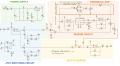
Hello Im tring to analyze a circuit and it has this switching circuit that I dont really understand (especially the diodes part ).
Can anyone help me ? Thanks !
It seems that the JFET is ON when the gate is left floating via D1 (D1 prevents the JFET gate to channel diode to conduct) and a positive voltage at the FS2 point. And when FS2 is at ground the JFES is OFF.
I suspect that the 10μF capacitor was add to slow down Turn ON and Turn-OFF time used to prevent "pop sound" when switching between ON/OFF.
And it is a mystery to me why they add into the circuit the D2+100k resistor in parallel with the 1k resistor.

 Facebook
 Google
 GitHub
 Linkedin


 Im tring to analyze a circuit and it has this switching circuit that I dont really understand (especially the diodes part ).