Question about BJTs and figuring out what mode it is in

Thread Starter

COMGUY123

Joined Apr 13, 2017
1
I am trying to do HW problems, but I seem to have an issue. How do you figure out what mode you are in? I understand that you need to figure out what Vb, Vc, and Ve are, but my issue is that wouldn't Vc be change depending on what mode you are in? For example, if the collector has a resistor and the emmiter goes to ground, Vc would be the voltage drop in active mode, but Vc would be close to 0V in saturation. The only way I can think of figuring this out is that you have to assume you are in a mode, solve it, and see if the numbers make sense. If the numbers do not make sense, that means it is not that particular mode. Am I ,missing something, or is this just what you have to do?
 

ericgibbs

Joined Jan 29, 2010
21,477
hi 123,
The Vb, Vc and Ve are only labels that are used to indicate where a voltage is measured with respect to the Common/0v line.

Does that make sense.?

E
 

shteii01

Joined Feb 19, 2010
4,644
I am at work and don't have my textbook right now.

If i recall, you have to make a couple assumptions. then set equations based on the assumptions. once you solve the equations, you check the answers against the mode definitions.
 

dl324

Joined Mar 30, 2015
18,403
Welcome to AAC!
How do you figure out what mode you are in?
The text book I used had a table listing modes which depended on whether junctions were forward or reverse biased.

If you're doing this from a schematic, you just need to determine voltages on the three terminals of the transistor. Until you become more familiar with modes of operation, you can look up the junction configuration in the table.

For an actual circuit, you just determine whether the junctions are forward or reverse biased.
 

WBahn

Joined Mar 31, 2012
32,965
I am trying to do HW problems, but I seem to have an issue. How do you figure out what mode you are in? I understand that you need to figure out what Vb, Vc, and Ve are, but my issue is that wouldn't Vc be change depending on what mode you are in? For example, if the collector has a resistor and the emmiter goes to ground, Vc would be the voltage drop in active mode, but Vc would be close to 0V in saturation. The only way I can think of figuring this out is that you have to assume you are in a mode, solve it, and see if the numbers make sense. If the numbers do not make sense, that means it is not that particular mode. Am I ,missing something, or is this just what you have to do?
That's exactly how you do it.

With experience and practice you will be able to make good first assumptions about what mode diodes, transistors, relays, and other components are in. But at the end of the day you generally need to make an assumption, solve the portions of the circuit that are relevant based on those assumptions, and then see if the solution is consistent with that assumption. If not, use what you have learned to made a better assumption for the next round.
 

MrAl

Joined Jun 17, 2014
13,726
I am trying to do HW problems, but I seem to have an issue. How do you figure out what mode you are in? I understand that you need to figure out what Vb, Vc, and Ve are, but my issue is that wouldn't Vc be change depending on what mode you are in? For example, if the collector has a resistor and the emmiter goes to ground, Vc would be the voltage drop in active mode, but Vc would be close to 0V in saturation. The only way I can think of figuring this out is that you have to assume you are in a mode, solve it, and see if the numbers make sense. If the numbers do not make sense, that means it is not that particular mode. Am I ,missing something, or is this just what you have to do?
Hi there,

Well i am not sure what level of detail you care to look into. You can start easy or jump right into it. If you jump right into it, you'll find the definitions are pretty clear and simple but the mathematics for it may or may not appeal to your liking. The math isnt that difficult because it doesnt involve anything more than algebra but it all depends what kind of math you are used to using.

So to start, we need a definition. There are four different modes but only two are more common. The definition of these modes comes from which junctions are forward biased and which junctions are reverse biased. Since there are two main junctions and two different bias directions, that gives us the four modes.

The most common mode is usually called the active mode or linear mode or something like that, and that is when the BE junction is forward biased and the BC junction is reverse biased.
The second most common mode is usually called the saturation mode, and that is when the BE junction is forward biased and the BC junction is ALSO forward biased.

Those are the most common modes but i must warn though that the way we get from one mode to the other is more like a feedback system and so there is a smooth transition from one mode to the other, based on smooth functions. So there are no sharp corners that take us from one mode to the other, but we usually think of it like that anyway to simplify the analysis and understanding of the devices. That brings up the question of what mode we are in, even though we may be in the gray area where we are transitioning from one mode to the other, more or less. The transition is usually quick enough though so we may consider that to be sharp in some situations.

Looking at it as a feedback system is a better way to explain it, along with two diode equations for the base emitter and for the base collector.
We can call the base emitter current the 'input current' for now and the collector emitter voltage the 'output voltage' which would be the output to the feedback system. The feedback comes from the base collector diode, and as the output drops with more base emitter current, we start to see a tiny base collector current start to flow in the opposite direction to the CB leakage current, and that steals current that otherwise would have driven the base emitter junction with a higher current, and that is what we might call the beginning of saturation. As more current is 'stolen' from the base emitter by the shunting action of the base collector current, the overall current gain necessarily drops. Thus we see much less 'gain' in 'saturation'. This is also how the Baker Clamp works, although that configuration 'fools' the transistor into 'thinking' it is in saturation while really it is not, so it puts it into a sort of false saturation mode.

If we had to define the point where we start to enter saturation we'd have to say that it is the moment where the collector emitter voltage drops below the base emitter voltage and so the base collector junction starts to become forward biased. The current will be very small then, but it will pick up as the collector emitter voltage drops more. The transition calculation comes from a diode equation and so given the base emitter diode equation we end up with a feedback system with two diodes and a current controlled current source. So although there is a time when we might say that we are in one mode or another, the feedback system would automatically handle that so there would not have to be a conscious decision to be made on our part, if we had the right defining equations on hand.

The two main equations are the two diode equations and a current controlled current source and there are also some internal series resistances to each terminal. It may be advantageous to determine by inequality when the base collector diode just starts to become forward biased so as to keep the two functions simpler. If we used the leakage current when the diode is reverse biased and then switch to the diode equation once the collector emitter voltage drops, that would handle all cases. The problem with an inequality though is that it may require an iterative process to produce the final value. On the other hand, the final solution will probably have to be solved numerically anyway. If we can choose the diode saturation current properly though we should be able to avoid the inequality. I'd have to look at this again myself too.

Of course there is also the 'off' mode where the base emitter diode is reverse biased and so is the base collector diode. That is of course common also in a switching circuit :)

Maybe we can look at a simple example.
 
Last edited:

MrAl

Joined Jun 17, 2014
13,726
Hello again,

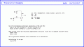
Here is a simple worked example. Note how the mode falls right out of the solutions for Vbe and Vbc, mostly Vbc.

Also note that this shows an approximate solution given a specific error bound. That means there will be a host of solutions on the dome of solutions within that error bound, but they should all be very close to each other in value so choosing one of them is usually acceptable.

Also note that the solution required using a numerical multivariate equation solver. I used the method of steepest decent for simplicity and was looking for a sum of squared errors around 0.001 also for simplicity.

Also note that no other components internal or external were used for this simple example.

Also notable is that the Beta had dropped to about 81.3 here in saturation.

I realize i put a lot of notes here, but one more of interest is that if the temperature changes the solutions can change by a significant amount.

I also realize that not everyone would want to do it this way or be that specific about the desired accuracy.

LATER:
A closer approximation done later came out to be:
Vbe=0.779472v
Vbc=0.701512v
therefore we end up with:
Vce=0.07796v
 

Attachments

Last edited:
Top