Facebook
 Google
 GitHub
 Linkedin
Hi All!
I have an old automotive battery charger that I have, for many years, used for electrolytic rust reduction. I never have had a problem until this week.
It is the non-automatic type (in other words, there is no circuitry to stop charging the battery when the battery has sufficient voltage). The other day, the unit failed so I opened it for diagnosis. That's where my confusion began! I should know the answers to my questions, but maybe I am having a 'slow brain' day today.
The failure was that one diode shorted cathode-to-anode in both directions. I think I must have accidentally shorted DC (-) and DC (+) by placing my anode & cathode too close together in the electrolytic bath (or used too much washing soda, the conductive chemical, in the water or had too large of an anode load in the bath).
I eliminated the bad diode and used the device again successfully. A day or so later, I had a second diode fail by shorting anode-to-cathode. I eliminated it. The DC voltage was lower than after only one diode was skipped, but the charger worked. (I don't know what the voltage was when all four diodes were in the circuit since I never measured it before the first failure.)
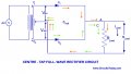
Note that the thermal circuit breaker shown in the attached diagram did not open upon diode failure. Instead, a melting link in the primary that is tucked into the transformer body opened. I replaced it with a piece of Sn 63 solder for the time being. It did its job and melted when the second diode failed. (Reasonably close in melt temp to the original, but not exact)
The device has a pair of SPDT switches that allow the user to select between 2 amp, 20 amp or 50 amp charging. The owner's manual says the 50 amp is limited to ten seconds of use. I assume that the 2 and 10 have 100% duty cycles.
At first glance, I thought that the transformer was center tapped because there are three terminals on the secondary. After some meter testing, it appears that this is not the case. The center terminal goes directly to the DC (-) and the two outer ones go to four diodes. I believe it is not center-tapped because the voltage between the two outer terminals is near zero (about 20 mV) no matter the position of the SPDT switches.
The four diodes are wired in parallel and line 2 of the transformer's secondary goes directly to DC (-). I think this arrangement is called Half Wave rectification because the transformer is not really center tapped and no diodes are on Phase Two of the transformer. I do get confused, however, because the frequency across DC (+) & (-) is 120 Hz. It seems to me that a half-wave rectifier circuit would show 60 Hz and Full-Wave & Full-Wave Bridge would show 120 Hz.
As far as amperage changes, all I can figure out (or guess) is that the switches select different amounts of primary windings, increasing the voltage, thus the available wattage & current. Why do I think this crazy stuff? Because I get different voltages between either of the outer terminals and the center terminal as the switches are closed or opened. For example, it will change from 9.45 vac to 11.73 vac when switching between 2 and 10 amps. It jumps to 13.88 when 50 amps is chosen. (With the two bad diodes bypassed.)
The Grand Plan is to remove the diodes and install a Bridge Rectifier (and maybe a smoothing capacitor just for fun). I'd connect it as explained in the lower left of my attached drawing. Part Two of the plan is to provide protection for the transformer.
My questions are:
A) Am I wrong & this really is a center tapped transformer? If so, why is the voltage between the outer terminals near zero?
B) How does the device provide more charging amperage to the battery being charged? Just by increasing the voltage output by selecting more or less primary windings?
C) Is this parallel diode arrangement called "Half Wave" since the two outer transformer taps are the same phase? (But why then is the frequency at the DC side 120 HZ, like a full-wave or bridge, instead of 60 HZ, like half-wave would provide?)
D) Do you have a guess of what the VA of the transformer is? There are no markings. My guess is something about 120 VA (10 amps x 12 nominal volts)
E) If I install a bridge rectifier and want a smoothing capacitor(s) across DC (+) and (-), do you have an idea of the micro farad required? I tried some on-line calculators, but get many different answers. (Form 2,000 mf to 100,000 mf)
F) I would like to protect the transformer with a fuse or breaker on the primary. I am having trouble deciding on a fuse size. At first, I thought a 2 amp fuse would be OK because the rating plate shows 1.87 amps at the 10 amp setting. But the trip curves for fuses & breakers show less than one second for a 50 amp load to open the fuse. The fuse's purpose is to stop the melt link from opening if (when) I goof up again. (If necessary, in order to protect the transformer, I am more than willing to eliminate the 50 amp selection. I don't use it.)
I apologize that the attached drawing is rather rough. I did it this quickly during this morning's cup-of-tea break.
Thanks for your suggestions & thoughts about this device & my questions. I sure appreciate your help!
Enjoy This Day!
Paul
I have an old automotive battery charger that I have, for many years, used for electrolytic rust reduction. I never have had a problem until this week.
It is the non-automatic type (in other words, there is no circuitry to stop charging the battery when the battery has sufficient voltage). The other day, the unit failed so I opened it for diagnosis. That's where my confusion began! I should know the answers to my questions, but maybe I am having a 'slow brain' day today.
The failure was that one diode shorted cathode-to-anode in both directions. I think I must have accidentally shorted DC (-) and DC (+) by placing my anode & cathode too close together in the electrolytic bath (or used too much washing soda, the conductive chemical, in the water or had too large of an anode load in the bath).
I eliminated the bad diode and used the device again successfully. A day or so later, I had a second diode fail by shorting anode-to-cathode. I eliminated it. The DC voltage was lower than after only one diode was skipped, but the charger worked. (I don't know what the voltage was when all four diodes were in the circuit since I never measured it before the first failure.)
Note that the thermal circuit breaker shown in the attached diagram did not open upon diode failure. Instead, a melting link in the primary that is tucked into the transformer body opened. I replaced it with a piece of Sn 63 solder for the time being. It did its job and melted when the second diode failed. (Reasonably close in melt temp to the original, but not exact)
The device has a pair of SPDT switches that allow the user to select between 2 amp, 20 amp or 50 amp charging. The owner's manual says the 50 amp is limited to ten seconds of use. I assume that the 2 and 10 have 100% duty cycles.
At first glance, I thought that the transformer was center tapped because there are three terminals on the secondary. After some meter testing, it appears that this is not the case. The center terminal goes directly to the DC (-) and the two outer ones go to four diodes. I believe it is not center-tapped because the voltage between the two outer terminals is near zero (about 20 mV) no matter the position of the SPDT switches.
The four diodes are wired in parallel and line 2 of the transformer's secondary goes directly to DC (-). I think this arrangement is called Half Wave rectification because the transformer is not really center tapped and no diodes are on Phase Two of the transformer. I do get confused, however, because the frequency across DC (+) & (-) is 120 Hz. It seems to me that a half-wave rectifier circuit would show 60 Hz and Full-Wave & Full-Wave Bridge would show 120 Hz.
As far as amperage changes, all I can figure out (or guess) is that the switches select different amounts of primary windings, increasing the voltage, thus the available wattage & current. Why do I think this crazy stuff? Because I get different voltages between either of the outer terminals and the center terminal as the switches are closed or opened. For example, it will change from 9.45 vac to 11.73 vac when switching between 2 and 10 amps. It jumps to 13.88 when 50 amps is chosen. (With the two bad diodes bypassed.)
The Grand Plan is to remove the diodes and install a Bridge Rectifier (and maybe a smoothing capacitor just for fun). I'd connect it as explained in the lower left of my attached drawing. Part Two of the plan is to provide protection for the transformer.
My questions are:
A) Am I wrong & this really is a center tapped transformer? If so, why is the voltage between the outer terminals near zero?
B) How does the device provide more charging amperage to the battery being charged? Just by increasing the voltage output by selecting more or less primary windings?
C) Is this parallel diode arrangement called "Half Wave" since the two outer transformer taps are the same phase? (But why then is the frequency at the DC side 120 HZ, like a full-wave or bridge, instead of 60 HZ, like half-wave would provide?)
D) Do you have a guess of what the VA of the transformer is? There are no markings. My guess is something about 120 VA (10 amps x 12 nominal volts)
E) If I install a bridge rectifier and want a smoothing capacitor(s) across DC (+) and (-), do you have an idea of the micro farad required? I tried some on-line calculators, but get many different answers. (Form 2,000 mf to 100,000 mf)
F) I would like to protect the transformer with a fuse or breaker on the primary. I am having trouble deciding on a fuse size. At first, I thought a 2 amp fuse would be OK because the rating plate shows 1.87 amps at the 10 amp setting. But the trip curves for fuses & breakers show less than one second for a 50 amp load to open the fuse. The fuse's purpose is to stop the melt link from opening if (when) I goof up again. (If necessary, in order to protect the transformer, I am more than willing to eliminate the 50 amp selection. I don't use it.)
I apologize that the attached drawing is rather rough. I did it this quickly during this morning's cup-of-tea break.
Thanks for your suggestions & thoughts about this device & my questions. I sure appreciate your help!
Enjoy This Day!
Paul
Attachments
-
72 KB Views: 13
Last edited: