Query method to eliminate spike during AC signal triggering on

Thread Starter

kw chong

Joined Apr 14, 2016
8
Hi,

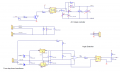
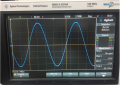
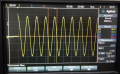
Does any way can eliminate spike during ac waveform trigger on?(Refer attachment file for example waveform)
There is 90 degree firing angle for ac waveform, spike happen at initial trigger of the firing angle.
Please advise.
 

Attachments

danadak

Joined Mar 10, 2018
4,057
What is source of sine, and how is it being gated ? Schematic would help.

One practice is to switch sign source at zero crossing.

Regards, Dana.
 

Thread Starter

kw chong

Joined Apr 14, 2016
8
Sine input is 100Vac supply from ac power source. Schematic attached.
Yes had use zero crossing method to switching using triac.
But there is a spike at sine during triac switch on.
Any idea?
 

Attachments

Thread Starter

kw chong

Joined Apr 14, 2016
8
scope probe is square wave on the calibrate port. No see under/overshoot.
Attached another waveform capture using another scope from my client site.
 

Attachments

Danko

Joined Nov 22, 2017
1,835
Hi,
never calculate. Too many parameters I need to measure for it.
Usually I start from "standard" 51 Ohm and 0.22 uF, see what happens with spike,
then, changing components, in 3...5 steps find optimal values.
HERE you can find all about snubber calculating.
 

ebp

Joined Feb 8, 2018
2,332
Before worrying about a snubber, consider whether there is anything to be gained in snubbing a small spike.

I would also suggest running the simulation so that it ends no later than the first zero crossing after the spike, so there is some hope of actually seeing some detail in the spike. Do the same when using an oscilloscope. You do need to have a quick look at subsequent cycles if you think there may be something odd, but filling the screen or window with a bunch of identical cycles simply hides detail that might be instructive.

As long as you are using a simulator, look at the current spike through the snubber - depending on the turn-on speed of the triac, it could be many amperes. In the circuit at #6 the snubber current spike through the snubber at turn-on will be very much greater than the current through the load.
 

Danko

Joined Nov 22, 2017
1,835
I would also suggest running the simulation so that it ends no later than the first zero crossing after the spike, so there is some hope of actually seeing some detail in the spike
@ebp: Now you can see all details in the spike.
As long as you are using a simulator, look at the current spike through the snubber - depending on the turn-on speed of the triac, it could be many amperes. In the circuit at #6 the snubber current spike through the snubber at turn-on will be very much greater than the current through the load.
@ebp: Since you have all the information about spike, what values of snubber's capacitor and resistor could you suggest to eliminate spike in time 56uS and dramatically reduce snubber current?
snubber-2.png
 

ebp

Joined Feb 8, 2018
2,332
Excellent plots! - especially the labels right on the curves.

The only way you can do anything about the current magnitude is if you are prepared to accept that part of the voltage spike will be allowed to remain. I would actually be very unconcerned with the original voltage spike since the magnitude just isn't very large. I suggest trying perhaps twice the resistance and half the capacitance. There is lots of room to allow the voltage with the snubber to increase without even getting up to the level of the curve without L1.
 

Danko

Joined Nov 22, 2017
1,835
The only way you can do anything about the current magnitude is if you are prepared to accept that part of the voltage spike will be allowed to remain.
Not allowed by TS.:(
I suggest trying perhaps twice the resistance and half the capacitance.
Below is simulation with parameters you suggested.
Transition process lasts 78us instead 56us.
Spike is partial reduced, not eliminated.
Snubber current reduced on 25% only.
snubber-3.png
 
Last edited:

ebp

Joined Feb 8, 2018
2,332
I'm sorry, Danko, I missed your response at #12 when you first posted it.

It is interesting that doubling the resistance has such a small effect on the peak current. I don't immediately understand why that should be the case.

It would be interesting to put a snubber across the triac instead of across the load. This is normally where a snubber is placed in such a circuit, but the intent is to prevent problems with the triac turn-off rather than any spike that might occur across the load.
 

Danko

Joined Nov 22, 2017
1,835
It would be interesting to put a snubber across the triac instead of across the load.
Here it is:
Spike on load is a bit lower with snubber, because of longer OFF>ON time from big current through triac.
EDIT: Seems snubber 10 Ohm 0.7 uF across load is better variant (post #6 ) because of full spike suppression and low power, dissipates by 10 Ohm resistor - 5 mW only (5 seconds triac ON, including start 5 A pulse).
snubber-4.png
 
Last edited:

ebeowulf17

Joined Aug 12, 2014
3,307
Just for fun I tried values from one of the few snubbers I'm familiar with, the QuenchArc line:
http://www.cde.com/resources/catalogs/Q-QRL.pdf
https://www.ttiinc.com/content/ttii...ubilier-Quencharc-Suppressor-Snubber-QRL.html

I've used the 0.1uF, 100 ohm snubber a lot, and those values seem to work pretty well. The spike can be reduced even a little further with 50 ohms (roughly 6V overshoot instead of 8V, at the expense of slightly higher snubber current, ~2A vs 1.2A.) This is with snubber across the load again, not across the TRIAC.

inductive-kick_snubber_2.png
 

Attachments

ebeowulf17

Joined Aug 12, 2014
3,307
What is the nature of the load? (Inductive motor, resistive heater, something weird like an SMPS?)

What is the load current? An approximate estimate is fine. 100mA, 1A, 10A...?

What is the control signal and how is it being handled? Is it still 5VDC? Is it on constantly when you want the load active, or is it pulsed in some specific phase angle relationship? (You mentioned before that you were using zero-crossing control, although your scope traces at that time showed TRIAC firing at 90 degrees.)
 

Danko

Joined Nov 22, 2017
1,835
Fundamental term in this topic is eliminate spike,
so if we are trying to reduce snubber current, we should
not forget that term.
In this circuit spike is eliminated and snubber current is about 1.8A:
snubber-5.png
 
Last edited:
Top