Facebook
 Google
 GitHub
 Linkedin
So Im trying to set up this circuit:

which came from this youtube video btw:
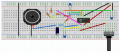
Ive made a Fritzing (and attached the fzz.zip file) of it since its the closest I can get to drawing what I have on the actual breadboard. The circuit doesnt work in the sense that it doesnt make the sounds it should. Here are a few caveats:
1. Im using a single 9V battery to power the circuit.
2. Im using a speaker from a wireless home phone.
3. Im actually using the 1uF cap (micro) before the speaker (a polarized type btw), but for the other caps Im using ceramic non polarized caps that are 0.047uF which have a "473" marking on it. I dont have 10nF, but 0.047 works to about 47nF so I figured Id give it a shot.
Im worried about my wiring on the breadboard so I made the fzz file so someone could review it and tell me if it represents the schematic posted above.
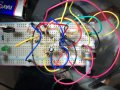
Ill post a picture of the breadboard but its a mess!")
Thanks in advance
which came from this youtube video btw:
Ive made a Fritzing (and attached the fzz.zip file) of it since its the closest I can get to drawing what I have on the actual breadboard. The circuit doesnt work in the sense that it doesnt make the sounds it should. Here are a few caveats:
1. Im using a single 9V battery to power the circuit.
2. Im using a speaker from a wireless home phone.
3. Im actually using the 1uF cap (micro) before the speaker (a polarized type btw), but for the other caps Im using ceramic non polarized caps that are 0.047uF which have a "473" marking on it. I dont have 10nF, but 0.047 works to about 47nF so I figured Id give it a shot.
Im worried about my wiring on the breadboard so I made the fzz file so someone could review it and tell me if it represents the schematic posted above.
Ill post a picture of the breadboard but its a mess!
Thanks in advance
Attachments
-
13.5 KB Views: 3
-
 212.1 KB Views: 6
Last edited: