[Q] Photodetector circuit connection to AC/DC power supply ?

Thread Starter

hwoarang

Joined Dec 28, 2015
18
Hello, guys in all about circuits.

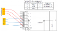
I am gonna use photodetectors which have three leads (+12Vdc, -12Vdc, GND). For their dc power, I think that I use a simple AC/DC power supply like the following link, http://www.jameco.com/webapp/wcs/st...Id=10001&ddkey=http:StoreCatalogDrillDownView.
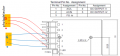
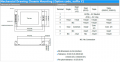
And the picture below is the circuit drawing from the datasheet of that product.
I think that the photodetector's three leads could be connected to the power supply like a picture without a problem, but the company said that it does not look proper. I didn't understand what they said.
So, do you think that it will have some problems ?
upload_2017-3-14_18-1-5.png

And another question is... my photodetector circuit runs at 0.5 amps, and the power supply above serves 1 amps (or other model ~ several amps). So, can I connect two photodetectors in parallel like the picture without a problem ?

Thank you all, in advance.
Have a good day today.

Best regards,
Jiwan.
 

Attachments

LesJones

Joined Jan 8, 2017
4,191
It is connected incorrectly. The "FG" terminal has nothing to do with the output. It is frame ground which should be connected to the mains earth. You need a power supply that provides a +12 V and -12V output with respect to a common terminal. ( This would connect to the ground terminal on the photodetector. ) You could also use two of the power supplies that you have. You would connect the positive of one to the negative of the other. This would be the common terminal. you would then have +12V and -12V with respect to the common terminal available. I suggest that you post the data on the photodetectors before connecting them up in case you have interpreted the data incorrectly.

Les.
 

Thread Starter

hwoarang

Joined Dec 28, 2015
18
It is connected incorrectly. The "FG" terminal has nothing to do with the output. It is frame ground which should be connected to the mains earth. You need a power supply that provides a +12 V and -12V output with respect to a common terminal. ( This would connect to the ground terminal on the photodetector. ) You could also use two of the power supplies that you have. You would connect the positive of one to the negative of the other. This would be the common terminal. you would then have +12V and -12V with respect to the common terminal available. I suggest that you post the data on the photodetectors before connecting them up in case you have interpreted the data incorrectly.

Les.
Thank you LesJones.
Do you mean that this power supply has no ground ? It would be not ok even though FG is connected to Earth ?
To use two power supplies is good way for me now. But to make it lighter, one wonder if there is any way to use just one power supply.
How about the following one ? In case of Dual channel, it has a common ground at terminal 5. Do you think this is gonna work ?
upload_2017-3-14_21-24-15.png

Regarding the photodetector circuit, I am sorry that I don't have it now. Just I have a plan to benchmark the commercial one like (https://www.thorlabs.com/newgrouppage9.cfm?objectgroup_id=3257#) and will change a photodiode (because of the response) and some resistors and capacitors (because of bandwidths). Maybe the design of the photodetector will be like this, I guess. Sorry for the rough design, it is not definite, but it would be something like this.
upload_2017-3-14_21-18-16.png

Thank you very much for the help.

Best regards,
hwoarang1
 

Attachments

LesJones

Joined Jan 8, 2017
4,191
The photodetectors in your link do require a + and -12 volts supply. The one in your circuit is also designed for a + and - 12 volts supply but probably could be modified to work with a single rail by consiering the negative supply to the op amp as ground and connecting the + input to a potential divider (Two equal value resistors.) between ground and +12. This would mean that the out put could only go positive with respect to ground. Would this meet the requirements of the circuit is driving ? The case of the power supply would be connected to mains ground but the output would be floating. You could connect the negative of the power supply to this ground and then the + terminal would be 12 volts positive wuth respect to ground. If you connect the positive terminal to this ground then the negative terminal will be -12 volts with respect to ground. Your signal ground and safety ground (Mains ground) do not have to be connected together although they normally are. I think designing a photodetector with 380 Mhz bandwidth wil be a great challenge. It would be interesting to know what data you plan to transfer over the link. (I originally thought it was just a break beam detector.)

Les.
 

Thread Starter

hwoarang

Joined Dec 28, 2015
18
The photodetectors in your link do require a + and -12 volts supply. The one in your circuit is also designed for a + and - 12 volts supply but probably could be modified to work with a single rail by consiering the negative supply to the op amp as ground and connecting the + input to a potential divider (Two equal value resistors.) between ground and +12. This would mean that the out put could only go positive with respect to ground. Would this meet the requirements of the circuit is driving ? The case of the power supply would be connected to mains ground but the output would be floating. You could connect the negative of the power supply to this ground and then the + terminal would be 12 volts positive wuth respect to ground. If you connect the positive terminal to this ground then the negative terminal will be -12 volts with respect to ground. Your signal ground and safety ground (Mains ground) do not have to be connected together although they normally are. I think designing a photodetector with 380 Mhz bandwidth wil be a great challenge. It would be interesting to know what data you plan to transfer over the link. (I originally thought it was just a break beam detector.)

Les.
Thank you, Les for the reply.
Actually, It will be used for the time-resolved femtosecond laser pump-probe measurement. So, I am going to change R and C to make a photodetector operating at 1, 3, 10, 330 kHz which are repetition rate of various lasers (that's reason why I want to, kind of, copy first the commercial product in the previous link). And the signal from this photodetector will be transferred to lock-in amplifier through BNC cable.
What I am still confused is that why the photodetector does not have to be connected to mains ground (Earth). If two leads coming out of the photodetector should be connected to a BNC connector, one lead should be connected to the signal line in BNC connector and the other lead should be connected to the ground line (outer part) in BNC connector. And this ground line is also connected to the ground line (outer part of input terminal) of Lock-in amplifier which is already earthed (or lock-in is not earthed ?).
Even in this case, is it true that the photodetector does not need to be connected to Earth ?
Sorry for this idiot question. -_-a

Best regards,
hwoarang1
 

LesJones

Joined Jan 8, 2017
4,191
All of your signals should be referenced to SIGNAL ground. This does not have to be the same as mains ground but usually is. One example of this would be the primary side of a switch mode power supply. If you were working on it trying to fix a fault you would probably consider the negative output of the input bridge rectifier as your reference point so you would connect the negative lead from your test meter to this point. THIS REFERENCE POINT (WHICH WOULD BE CONSIDERED THE LOCAL GROUND.) MUST NOT BE CONNECTED TO MAINS GROUND. This is because the mains neutral is connected to ground (Rods or plates buried in the ground.) at the substation. If it was then the bridge rectifier would be shorted out. This is the reason that a switch mode power supply MUST be fed via an isolating transformer with a floating secondary if you need to use an oscilloscope for testng the primary part of the power supply The ground side of the oscilloscope will be connected to mains ground. Providing you can trust the insulation on the power supply to the photodetector it is better not to connect it to the mains ground lead to the power supply as this could introduce noise on the signal if the ground that your lock in amplifier is connected to is at a slightly different potential to this power supply.

Les.
 

Thread Starter

hwoarang

Joined Dec 28, 2015
18
Thank you very much, Les.

It seems that there are some photodetectors operating with potable batteries (+V and -V). I am not sure if one common lead is connected to Earth. But it is not necessary to do that as you said, I guess. In this sense, maybe I need to find AC/DC power supply with +V, -V, ~0 (not GND). Am I saying right ?
I appreciate your comments. :)

Best regards,
hwoarang1
 

MaxHeadRoom

Joined Jul 18, 2013
28,703
Thank you very much, Les.

It seems that there are some photodetectors operating with potable batteries (+V and -V). I am not sure if one common lead is connected to Earth. But it is not necessary to do that as you said, I guess. In this sense, maybe I need to find AC/DC power supply with +V, -V, ~0 (not GND). Am I saying right ?
I appreciate your comments. :)

Best regards,
hwoarang1
It is far clearer if the term Common is used instead of Ground where, in N.A. especially, it is used for both Circuit Common and Earth Ground.
Also the symbol (mis)used is generally always Earth instead of chassis or logic common.
Hence the confusion from the start of the post.
Max.
 

Attachments

Top