 Facebook
 Google
 GitHub
 Linkedin
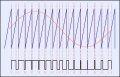
Hi guys! I have an audio signal and i want to generate PWM modulation of this audio signal. please see attached pic. i want to generate such kind of wave form using ATmega tiny or any other micro controller..please guide me
Attachments
-
 69.1 KB Views: 23


